Provision of information
A full set of design drawings and specifications shall be made available to the Warranty Provider and all other interested parties prior to the associated works starting on site. This may include:
- Timber and other wood based materials need to comply with the relevant requirements of BS EN 942. Evidence of this needs to be provided to the Warranty Surveyor.
- Evidence that the external windows and doors are suitable for the site exposure e.g. a manufacturer’s declaration of performance for the site.
- Evidence of certification confirming weather-tightness rating as detailed within BS 6375. External bespoke timber windows and doors that cannot provide a BS 6375 rating will need to be water tested as per CWCT Note 41.
- Evidence of UKCA marking in accordance with UK Construction Production Regulation.
- Details of external window and door fixing will be required.
- Details of sealing around the frame will need to be confirmed.
- External bespoke timber windows and doors must provide a detailed specification of the design, construction, and durability of the proposed units. Bespoke timber windows will not be acceptable for use without prior approval from the Warranty Surveyor.
The Warranty surveyor, at their discretion, may also request supporting information that demonstrates suitability for use of any materials or systems contained within the above.
What is an IGU?
Insulated Glazing Units (IGUs)
An Insulated Glass Unit, often referred to as a ‘double glazed unit’, is a combination of two panes of glass spaced apart with a spacer bar and sealed to form a single airtight unit with an air space in between.
The difference between double and triple glazing is as the names suggest. Triple glazing has an additional pane of glass, thereby creating air two spaces instead of one. The extra glass pane and gap increase the window's heat and sound insulation properties compared to double glazing.
IGUs have often included Low Energy coatings to the inner pane and gas fill (such as argon) in the space in between panes of glazing that make up the unit.
The use of Insulated Glazing Units (IGUs) referred to as ‘double glazing’ has been common within timber windows for a number of years. In the coming years, it is likely that an increase in the use of triple glazed units will become common practice to meet growing fabric energy standards.
Approaches to glazing with IGUs
BS 8000-7 Workmanship on building sites — Code of practice for glazing’ covers various methods that are applicable to the installation of IGUs. Of these however, within timber framed windows, we are likely to encounter the following approaches to glazing in most instances.
Glazed from the outside using glazing tape with a drained and ventilated beading system
IGUs are installed on setting blocks and secured using proprietary self-adhesive glazing tape. The external glazing beads can be timber or even aluminium, but all incorporate a gasket which exerts pressure on the IGU face to create a weatherproof seal when fixed into position.
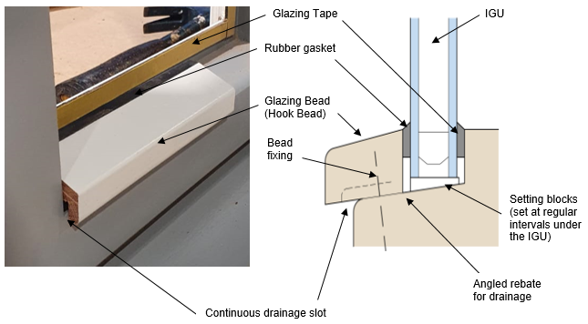
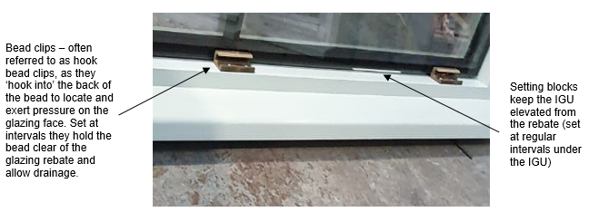
The lowest horizontal bead is set down on proprietary bead clip which holds the bottom bead higher than the surface of the glazing rebate to create a slot which allow drainage of water from the rebate. Note: Often the bottom bead is referred to as a ‘hook’ bead, as they ‘hook’ or locate into the clip system they are installed upon, often referred to as a ‘hook bead clips’.
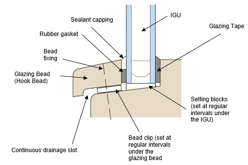
Glazed from the outside using glazing tape and sealant capping with a drained and ventilated beading system
IGUs are installed on setting blocks and secured using proprietary self-adhesive glazing tape. The timber external glazing beads incorporate a tape which exerts pressure on the IGU face when fixed into position.
The joint between the face of the glazing and the glazing bead then receives a capping of a one or two part curing sealant. The lowest horizontal bead must allow drainage of water from the rebate.
Common failures in IGU installation
One or more of the following are often present in failing installations. Each can contribute in allowing water to enter the glazing rebate and become trapped in the area under the glazing. This eventually causes IGUs to fail, or allows water to enter concealed parts e.g. the joints, eventually finding a passage to the inside face of the window. In winter, any trapped water can freeze contributing to the IGU’s seals failure and it is not until the spring where misting in the IGU’s occurs, can the issue be seen.
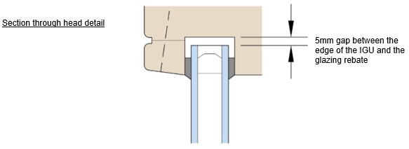
No allowance for drainage
The IGU has been set too close or touching the rebates of the frame and inhibits the drainage of water. A 5mm drainage path between the edge of the IGU and the rebate should be provided all round the IGU perimeter as this space allows any water that does penetrate seals to run to the bottom of the glazed area where it can drain out.
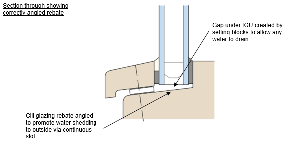
No setting blocks under the IGU
IGUs should be set into position using location and setting blocks. These blocks should be placed at intervals around the perimeter of the IGU. The spaces in between allow for any penetrating moisture to run to the bottom rebate and drain out.
The upper surface area of the cill rebate should be angled at a 1:10 (approximately 5.5° angle) so that any water driven into concealed spaces is directed out to the external face via a continuous drainage slot.
Failing glazing beads
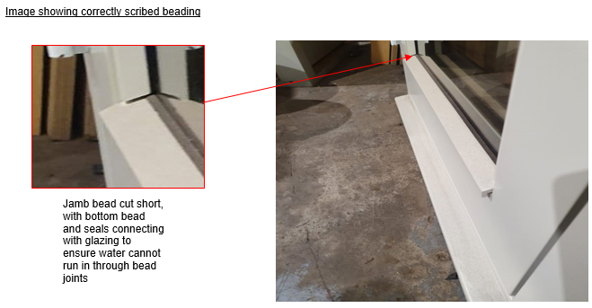
Mitred beading often leads to joints opening in service giving a direct path to moisture at corners. At the junction of bottom bead and vertical beads, water penetrating this area either becomes trapped or is directed into concealed areas of the frame.
To ensure robust and sustained weatherproof details, glazing beads should not be mitred at joints but cut squarely. The top horizontal glazing bead should run the full width of the opening to protect the top of the jamb beads on either side and the wider bottom bead should also run the full width of the opening and project to conceal the drainage weep slot provisions below.
The side (jamb) beads should be cut to stop short of the bottom bead by 3mm – where the bottom bead has a 1:6 (11° angle) weathering slope on its top surface, the gap can be reduced at the glass face by cutting the ends of the side beads to a shallower pitch.
The glazing beads should be securely fixed with non-ferrous pins or screws at a 200mm maximum spacing, starting at 50mm from corners to create a compression seal between the bead and the glass surface.
Incorrect use of sealant
The designed system of glazing has not been followed, and sealant has been used where it was not intended. Various systems can be used to seal contact points between glazed unit faces and beads e.g. self-adhesive dry glazing tapes, extruded gaskets, butyl tapes/gaskets with sealant capping. Importantly however mixing and matching approaches should be avoided and the ventilated and drained system must follow that proposed within designs.
On site operations that incorporate site applied capping sealant on drained and vented glazing systems should be executed in strict accordance with the design and specification.
Incorrect specification of sealant
In instances where butyl tapes/gaskets with sealant capping has been used, the use of an incorrect sealant specification can be the cause of many failures. Any voids that are created by shrinkage or lack of adhesion of the sealant will allow water through or become trapped resulting in water ingress or failure of the IGU.
Warranty stance
For the purpose of warranty:
- Ensure that full specifications have been made available – in the event of a review as part of the risk management process, they should demonstrate how the aforementioned failure items have been avoided.
- Fully bedding glazing units on sealant should not be accepted as a method to install IGUs as it leads to failures.
- Drained and ventilated bead systems must be used for installation of Insulated Glazing Units.
- Window systems should be supported by relevant testing – refer to Provision of Information for details.
- The Warranty surveyor should receive sufficient information on the drained and ventilated beading system and how it is installed as part of the specification package for the windows – this must be followed.
- Timber windows should be preferably supplied to site fully finished and fully glazed to minimise the opportunity for moisture ingress to affect any part of the window during the build stage.
