
Background
The term GRP stands for Glass Reinforced Polyester often referred to as fibre glass and is a composite material formed by a resin and fine fibres of glass. A curing agent, often referred to as a ‘hardener’ is used to turn the liquid resin into a solid over a short period of time, typically 30 - 60 minutes dependent on percentage of curing agent and ambient air temperatures.
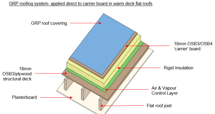
The approach of direct application to a timber substrate is commonly used on smaller roofs at a size equal to or less than 50m2 in area. GRP roofing systems in these situations are typically applied directly to timber decks or carrier boards, which are typically OSB/3 or OSB/4.
On larger roofs, it is far more common to see alternative types of liquid membranes such as flexible polyester (also referred to as multi surface GRP), PU or PMMA being installed using a carrier membrane layer rather than direct to a timber substrate.
Getting it right and avoiding common issues
GRP as a roofing system has been around for decades but we often see issues with its specification and installation, which can lead to premature failure. Common issues encountered are:
- Incorrect build-ups and poor detailing.
- Incorrect deck and carrier board specification.
- Poor installation of timber decks.
- Incorrect expansion gaps in structural deck and carrier boards.
- Incorrect fixings for the timber deck.
- Compatibility with other materials.
- Incorrect working practices – lack of surface preparation, poor application techniques, working in incorrect weather conditions.
As with any flat roof system, it is important to note that all these common issues can easily be avoided. The following sections are guidance on how to manage such risks.
Using correct build-ups and detailing
For the purposes of Warranty, a warm flat roof build up is recommended for all site applied GRP roof systems, but proposals must always be supported by a Condensation Risk Analysis calculation.
A specification and section drawings should be produced by the system manufacturer for all aspects of detailing specific to the project.
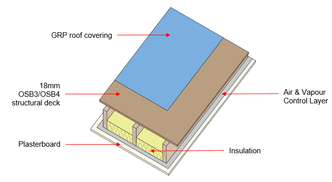
GRP - applied direct to structural timber deck in cold deck flat roofs
In a cold flat roof configuration, the GRP roof system would be applied directly to the structural timber deck.
This approach is restricted to roofs that are a maximum of 3m2 in area and have ventilation path lengths that are no greater than 5m e.g. distance from eaves to eaves.
Correct specification and installation of the structural timber deck
For the purpose of Warranty, when OSB is specified, the decking board must be manufactured to BS EN 300 and it must have UKCA marking. Alternatively, if plywood is used, it should conform to BS EN 1995 1-1 Euro code 5 and to BS EN 636 to a minimum service class 2 for humid conditions.
In all instances the decking board should be a minimum thickness of 18mm.
Decking boards should be laid in a staggered pattern, with board joints flush (surfaces within +/- 2mm). In all instances the material should be a minimum thickness of 18mm.
The orientation of the board will be governed by the material selection - plywood should be laid with the exposed face grain direction perpendicular to the supports. OSB should be installed over supports in the direction indicated on the boards, with the stronger axis installed at right angles to the supporting joists.
If squared edged decking boards are used, all sides of the boards must be supported on joists or noggings, with movement gaps of 3-5mm between boards. If tongued and grooved boards are selected, then they should be installed with their long edges at right angles to the supporting timbers, and short edges supported on a joist or nogging. In both instances, any cut edges situated along the roof perimeter or within the roof area that do not coincide with joists must be supported on noggings with movement gaps of 3-5mm between boards.
Decking boards must be adequately fixed and supported along edges on supporting timbers. At joints, board edges should be set centrally over the supporting timber to ensure that equal support is provided to each board edge and fixings achieve the required purchase into the supporting material.
The minimum decking board bearing onto a supporting timber is 18mm at board joints, with a full bearing for the width of the supporting timber achieved at perimeter or abutment detailing.
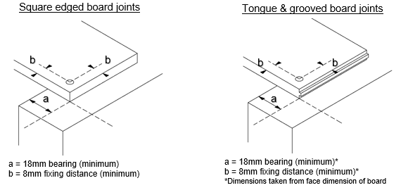
Fixings should be at centres not exceeding 100mm at the perimeter or along any intermediate support, located at least 8mm from the board edge and should be made from corrosion resistant materials such as galvanized or sherardized steel, austenitic stainless steel, phosphor bronze and silicon bronze.
Where nails are used, nail heads should be punched 2-3 mm below the surface of the board and be selected based upon the material being fixed, so:
For OSB and plywood decking, fixings should be:
- A minimum of 50 mm or 2.5 times the thickness of the board, whichever is the greater, and the diameter of the fixing should be a minimum of 0.16 times the thickness of the board.
For plywood decking, fixings nails should be either:
- Plain wire nails at least 3.35 mm in diameter and at least 65 mm long, which penetrate at least 40 mm into the support, or,
- Annular-ringed shank nails at least 3.35 mm in diameter and at least 50 mm long, which penetrate at least 32 mm into the support.
Where screws are used, they should be pre-drilled and countersunk. The length and gauge of the fixing screw should be equal to or better than the performance of nail fixings.
Allowing for structural deck expansion
Expansion gaps must be incorporated into the structural timber deck installation to allow for thermal movement.
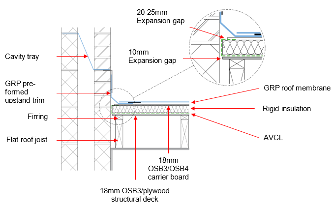
A minimum gap of 10 mm, or 2 mm per metre run of panel, whichever is the greater, should be provided around the perimeter of roofs to rigid upstands or abutting construction.
Intermediate expansion gaps should also be provided for larger flat roofs (in excess of 10m in width or length) at 2mm per metre run. This needs to be specified by a Structural Engineer with details on the size and location of the intermediate expansion gap.
At board joints, a minimum 3-5mm expansion gap needs to be maintained around all board edges.
Specification of insulation and moisture control in warm flat roof construction
For any roof design it is important to ensure that condensation risk is considered and the insulation choice is identified by the GRP manufacturer within the specification. It must be supported by a Condensation Risk Analysis calculation that has been carried out for the site specific roof design and building use.
Typically, the type of insulation used for GRP systems is a foil faced rigid board which then receives a carrier board fixed through into the supporting structure. Proprietary boards that offer a deck, insulation and AVCL in one product should only be used where the GRP manufacturer has agreed they are suitable for their roof membrane system.
The type of AVCL will be detailed in the Condensation Risk Analysis (CRA) calculation, which has been completed for the site specific roof design and building use. If a generic AVCL has been referenced within the CRA calculation, then the GRP manufacturer should recommend a suitable material prior to work commencing.
The AVCL must be continuous over the structural timber deck, and installed with all laps and penetrations completed in accordance with manufacturer’s instructions, prior to installation of insulation.
Workmanship is key to a successful installation in all instances, and notably so for warm flat roof build ups where it is critical to keep areas dry during construction to avoid trapping moisture within layers prior to application of the final GRP roofing membrane. As such, it is essential to have demonstrable Quality Assurance plans to ensure that procedures are in place in to deal with any adverse weather events and monitoring of work practices is at the forefront of delivering the ‘as designed’ performance levels.
Correct specification and installation of the carrier board
As GRP forms a chemical bond with the substrate, the facing and grade of the carrier board is critical and due to the wide variety of product available, it is important to follow the manufacturer’s guidance.
Typically manufacturers will require a high quality facing to the board with an open grain structure to allow good penetration of the resin.
Oriented Strand Board (OSB/3 or OSB/4) are the two most common material types endorsed by GRP manufacturers. Where plywood is used, the GRP manufacturer must approve its use for their system in the site specification as the variable nature of plywood means that many grades may not be suitable for use. Typically, hardwood facings and marine plywood should usually be avoided.
For the purpose of Warranty, when OSB is specified for the carrier board, it must be manufactured to BS EN 300 and it must have UKCA marking. Alternatively, if plywood is used, it should conform to BS EN 1995 1-1 Euro code 5 and to BS EN 636 to a minimum service class 2 for humid conditions. In all instances the carrier board should be a minimum thickness of 18mm.
The GRP manufacturer’s specification and application instructions should always be consulted on fixing requirements of the carrier board. Corrosion resistant thermally broken screw fixings may be necessary to reduce any thermal bridging that can occur through the attachment point between the carrier board and the corresponding supporting timber joists or noggings.
Fixings centres and board edge fixing distances should be as per the manufacturer’s specification and any supporting wind load calculations. The screw must fix into the supporting joist or nogging located beneath the lower structural deck by a minimum of 40mm.
Allowing for expansion in the GRP roof membrane system
On a cold flat roof deck (refer to limitations above for cold deck applications), where the GRP roofing membrane is applied directly to the structural timber deck, expansion allowances will be as per the guidance given previously for structural decks. Additionally, timber board joints will require local reinforcement with the GRP membrane prior to any base coat application, and reference should always be made to the manufacturer’s guidance on how this is to be achieved in terms of product and particular detailing.
On a warm flat roof, where the GRP roofing membrane is applied directly to a carrier board, the GRP manufacturer’s specification and application guidance should always be consulted regarding any requirement for expansion gaps.
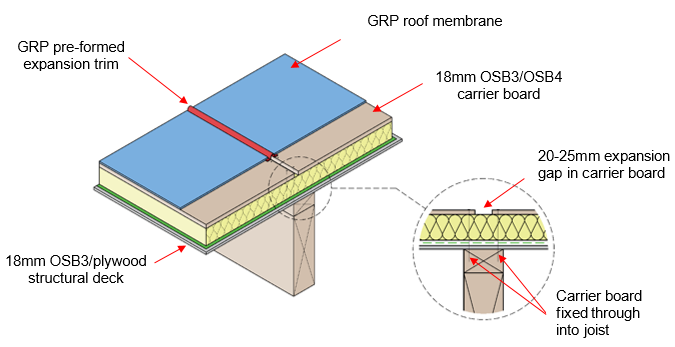
Typically where a timber carrier board is being used, many GRP manufacturers recommend a gap of 20-25mm be provided around the perimeter of roofs to rigid upstands or abutting construction. Board joints require a minimum 3-5mm expansion gap around all board edges, with any square edged board joints locally reinforced with the GRP membrane prior to base coat application.
Typical abutment expansion detailing – warm roof
Intermediate expansion in the GRP roof membrane system
For larger roofs, and dependant on GRP system selection, manufacturers may require incorporation of intermediate expansion detailing. Typically 20-25mm is used on roofs in excess of 50m2 area, or for roofs in excess of 10m in width or length. Their position will be referenced within the site design.
Such approaches must be facilitated by the use of proprietary expansion trims and installed in accordance with manufacturer’s instructions and detailing.
The use of Approved Installers
As with any flat roof system, it is important to note that common issues such as poor application techniques or applying during adverse weather conditions are often the reason for failure. Such instances can easily be avoided by using trained installers that are competent in their understanding of the product/system and follow the manufacturer’s guidance around application temperatures, and other external conditions that can affect performance.
Approved Installers should have demonstrable ‘Quality Assurance’ plans in place to ensure that procedures are in place to deal with any adverse weather events and the monitoring of work practices is at the forefront of delivering the expected performance levels.
For the purpose of Warranty, a flat roof system manufacturer’s Approved Installer must be used for all flat roof coverings.
Evidence of the manufacturer’s approval of the contractor to install their products should be provided to the Warranty Surveyor. Typically, this is in the form of an identity card, which features the installer’s name; a passport-style photograph; a unique card number; an expiry date; the manufacturer’s name and logo; and lists the products and/or systems for which the installer has been trained.
Testing of completed flat roof installations (all types of waterproofing systems)
Testing is required in the following situations:
- On low rise housing: Detached/semi-detached/terraced housing 3 stories or less in height (including the ground storey) when:
- The roof areas exceed 50m², or;
- Where the project consists of 10 or more properties: one test per ten houses (with a minimum of two tests per site) are required.
- On large developments: Apartments etc. over 3 stories in height (including the ground storey), where the total combined roof areas exceed 50m². In this case, a minimum of 20% of the roof areas must be tested.
- On developments involving our Major Projects Team, all flat roofs will require low voltage testing.
- Where, after completion of the site risk assessment, the Warranty Surveyor has identified areas of complexity in relation to the roof and its ancillary components that present a higher risk to Warranty (e.g. service penetrations, abutments with claddings, and penetrations from fixed items such as man safe systems).
These areas of complexity may be resultant elements of,
Design, where:
- The roof includes features beyond a typical wall abutment e.g. (but not limited to); variations of upstand constructions/penetrations/fixings/external permanent machinery/balustrading fittings etc.
- The waterproof membrane is to be covered over (by pedestrian finishes or solar panels). Note: Inverted roofs of straightforward design and with continuous hot-applied waterproof membrane could be exempted.
Construction, where:
- There are to be/have been, follow on trades on the roof after completion of the roof covering.
- Secondary items such as fall protection devices, PV supports, balustrades etc. are to be attached.
In all circumstances, testing should be carried out when the first flat roofs are completed in order to determine if there are any inherent issues with the design or workmanship. Where there is a failure, the root cause should be determined and appropriate remedial actions should be taken. The Warranty Surveyor may request an increase in the amount of testing required.
Resisting fire spread over roof coverings
All roof coverings will be required to satisfy regional Building Regulations in relation to fire performance. Evidence of fire performance should be included within the specification documentation and manufacturer’s fire test classification should be checked if in any doubt.
This should meet the minimum provision related to boundary distance given in statutory guidance; achieving European classification from BROOF (t4) to FROOF (t4) in accordance with BS EN 13501-5 from test 4 (t4) evidence.
Compatibility with other materials
GRP does not always adhere well to materials such as lead or concrete. As such, the GRP manufacturer’s guidance should always be sought prior to works taking place. Incompatible material will often need special preparation and need to be primed with a system specific primer to facilitate a good adhesion of the GRP to the material in question.
Warranty position
In all cases, where a GRP roof system is proposed:
- It must be covered by a full 3rd Party product conformity approval certificate.
- The Warranty surveyor will require a full specification for the proposed works prior to commencement on site – this must be accompanied by a full set of drawings covering all aspects of detailing.
- The specification and installation must be aligned with the content of the approval certificate and the manufacturer’s guidance.
- The installing contractor must provide evidence of inclusion into an Approved Installer scheme, which is controlled and verified by the system manufacturer.
