
Warranty aims:
Our primary aim is to focus on preventing water from entering the parapet wall structure. In the event that water does enter the parapet, the construction must include appropriate measures in place to discharge any water ingress from the wall and ensure it does not affect the building fabric.
This article introduces the principle of adopting a ‘3 lines of defence’ approach to creating robust and executable detailing at this critical area of building fabric.
Definitions have been used from BS 5642 - Sills, copings and cappings
- Coping - Construction that protects the top of a wall, balustrade, or parapet and sheds rainwater clear of the surfaces beneath.
- Capping - Construction that protects the top of a wall, but does not shed rainwater clear of the surfaces of the wall beneath.
The proportion of claims relating to water ingress due to failed coping detailing is extremely high compared to other claims and therefore considered a high risk element of construction that needs careful detailing on site. Parapets are more exposed to the elements, regardless of the climatic exposure of the site and hence more prone to failure.
Principal failings of coping installations continue to be:
- No damp proof course (DPC) provided below copings
- DPCs that are provided are unsupported and/or insufficient width to cover across the whole parapet
- Cavity trays beneath coping non-existent or poorly installed
- No weep holes
- Poor pointing between coping
- Pressed metal copings used, with over-reliance on mastic or fixings with no gaskets. Often installed without any DPC below
- Non-proprietary systems being used without third party accreditation
Contents
Section 1 - The ‘3 Lines of Defence’ Principle
1.1 Introduction
1.2 Risk Strategy
1.3 The ‘3 Lines of Defence’
Section 2 - Parapets to masonry and framed structure
2.1 Identifying and investigating failures
2.2 Defence line 1: The coping
2.3 Defence line 2: The horizontal damp proof course
2.4 Defence line 3: The cavity tray
2.5 Variations to the ‘3 Lines of Defence’
2.6 Additional Considerations for terrace guarding
Section 3 - Raking parapets to masonry and framed structure
3.1 Identifying and investigating failures
3.2 The ‘3 Lines of Defence’ principle in raking parapets
3.3 Defence line 1: The raking coping and capping
3.4 Defence line 2: The raking damp proof course
3.5 Defence line 3: The stepped cavity tray
Section 4 - Workmanship and Quality Assurance 22
Warranty position
Section 1 – The ‘3 Lines of Defence’ principle
1.1 Introduction
This is a supplementary guide to the LABC Warranty Technical Manual and relates to all ‘new build’ parapet wall constructions including flat roof, terrace and balcony parapet walls, irrespective of height.
1.2 Risk strategy
The primary aim is to design and provide an effective construction to prevent water from entering the parapet wall. However, with such high risk types of construction, additional measures must be incorporated for warranty purposes should water enter the parapet. The additional measures should prevent water from coming into contact with the inner leaf and reaching the habitable parts / internal finishes of the building.
1.3 The ‘3 Lines of Defence’ principle
When considering the parapet wall, we are faced with a structure that is exposed to the effects of weather on both sides and at its head. Often incorporating a capping, coping or balustrade system, the designs and methods adopted to weatherproofing this critical element are placed under an increased performance requirement.
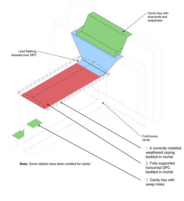
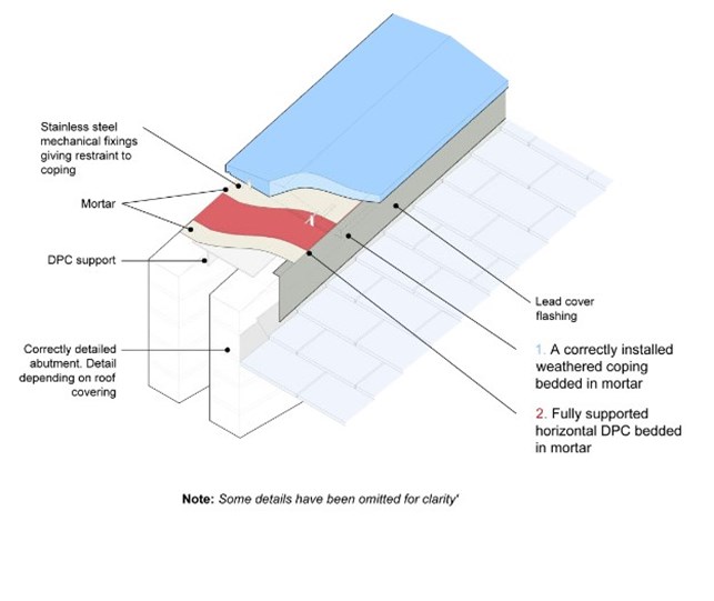
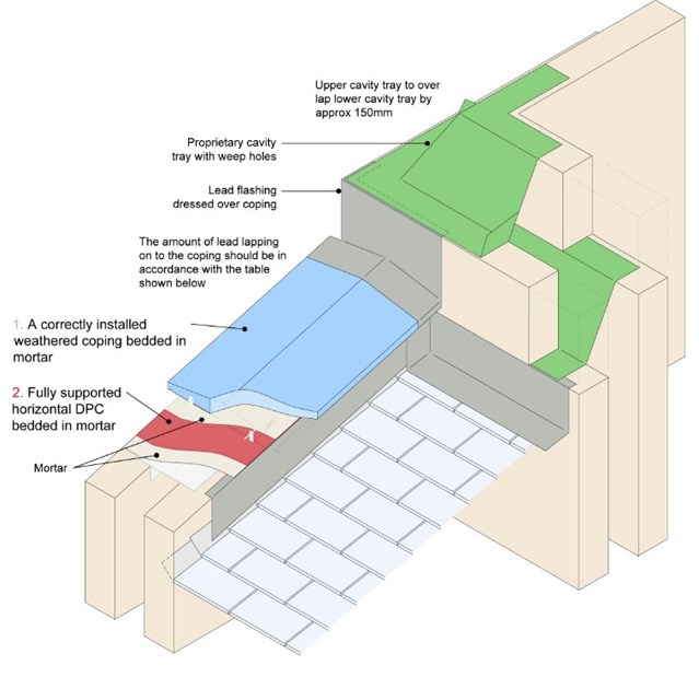
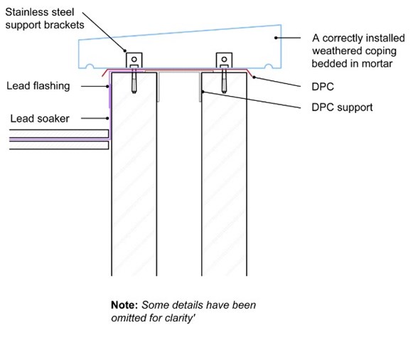
In the following detail, the ‘3 lines of defence’ principle is highlighted as three distinct areas of focus in a parapet wall construction:
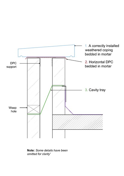
- Coping/capping - A correctly installed, weathered coping or capping with robust weatherproof connections.
- Horizontal DPC - A fully supported DPC, with sealed joints at laps, intersections and any penetrations.
- Cavity tray - A correctly installed cavity tray, with sealed joints at laps, complete with weep holes.
Section 2 - Parapets to masonry and framed structure
2.1 Identifying and investigating failures
In the event of water ingress through parapets, invasive investigations often reveal failings in the detailing and overall execution of these critical areas of construction.
Commonly occurring issues are highlighted below, categorised under their position in the ‘3 lines of defence’ principle.
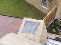
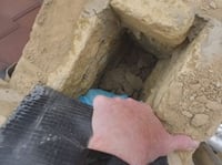
Failure of defence line 1: Copings and capping
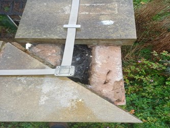
The first image above represents a situation where the DPC and DPC support has been omitted. As a result mortar bedding is not present and the copping has detached. The second image above represents a situation where the DPC has been omitted and the capping has been attached using mastic. Adhesion has failed and the lack of mechanical fixing has resulted in detachment and water ingress.
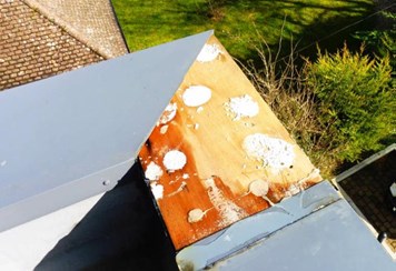
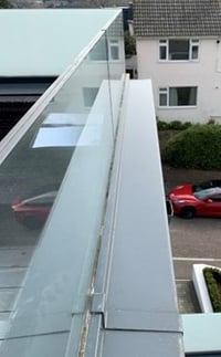
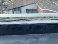
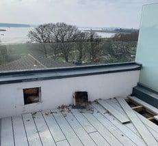
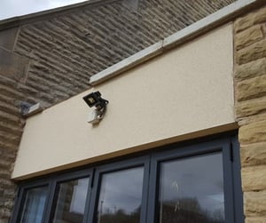
The images below depict a project that is less than two years old. The powder coated aluminium parapet capping has been shaped to encase the base channel of the frameless glass panels. This base channel has been fixed into the structure below creating penetrations. The drainage provision has been blocked and this has diverted water into the structure below.
The second image below also shows a glazing sealant has then been applied which has also failed in service.
The third image below is the resultant invasive checks that were carried out during the investigation.
Failure of defence line 2: Horizontal DPC
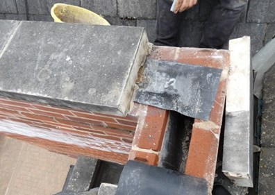
Failures in the horizontal DPC are common place. In the first image above, we can identify a DPC of incorrect width, a lack of support to the DPC as it crosses the cavity and a lack of sealed joints in the DPC. The second image above shows a complete omission of the DPC, which has compounded the cavity tray issue (described below).
Failure of defence line 3: Cavity trays

The cavity tray provision is the third and final line of defence in parapet construction. The failures range from poor cavity tray joint detailing, inadequate support and incorrect or lack of adequate provision for removal of trapped from the cavity.
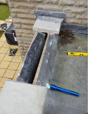
In the images above, the cavity tray has been incorrectly set to fall from the outer leaf to the inner leaf to avoid installing weep holes through the render. As a result, water entered the cavity and reached the building fabric below.
Back to contents
2.2 Defence line 1: The coping
Firstly, a coping is a construction that protects the top of a wall, balustrade, or parapet and sheds rainwater clear of the surfaces beneath. Copings can be formed using masonry or pressed metal profiles.
- All parapet walls should be provided with a suitable coping construction, which:
- Is capable of shedding water - a minimum two degrees fall from horizontal is required at the top surface of a coping. A coping without a fall is not permitted
- Creates an overhang on the face of the wall beneath - a minimum of 40mm, on each side must be achieved
- Incorporates a throating or drip provision
- Has a robust and durable jointing procedure
- Incorporates weather tight detailing to junctions with other elements of structure e.g. coping terminations abutting perpendicular walls
Where masonry coping units are being used, they must:
- Be frost resistant
- Be bedded and pointed using an appropriate high durability mortar, subject to the supporting masonry type (see Appendix C1 of the LABC Warranty Technical Manual). The mortar specification will be dependent upon the type of masonry unit being installed
- Include anti capillary or drip grooves to their underside – typically set back 10-15mm from the outer edge, and typically sized at 12mm wide x 8mm deep
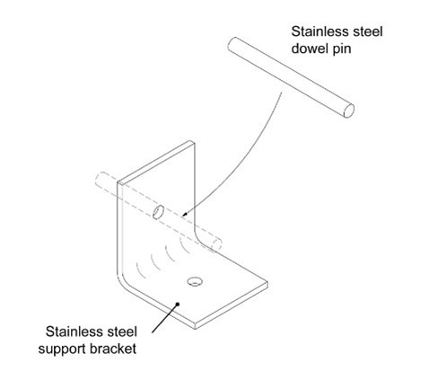
Where horizontal masonry copings are required to be mechanically fixed by the design engineer i.e. where they are forming part of the guarding, or where they may become displaced by lateral loads or vandalism or maybe subject to high wind pressures, they should be fixed using stainless steel fixings / dowels / bracketry. An A4 grade is required in coastal locations.
- Transfer any construction or movement joint in the supporting structure below, through the masonry coping stone. Any horizontal DPC and cavity tray arrangement must be continuous at the movement joint. In addition, the coping manufacturer’s requirements for the provision of movement of the coping itself (e.g. thermal expansion) must also be met.
- Masonry copings should not be used in conjunction with timber frame/SIP construction due to concerns over maintaining weather tightness and allowance for differential settlement in the timber frame.
Where pressed metal coping units are being used, they must:
- Be suitably durable for the exposure conditions on site and will achieve a minimum 15 year durability, inclusive of fixing elements e.g. screws, cleats, fixing bracketry.
Bi-metallic corrosion must be considered between the fixing and any pressed metal system. Consideration must be given to any aggressive environment affecting the site e.g. coastal locations, industrial zones, etc.
Aluminium coping systems must not be installed in contact with copper or its alloys, or the runoff from them – notably, attention should be given to the effect of any lightning conducting fittings attached to or in proximity to pressed metal copings.
Aluminium copings should not be bedded into mortar or concrete.
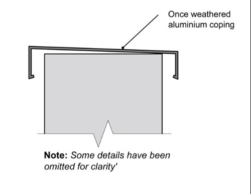
- Be ‘once weathered’ and incorporate pre-formed drip provision within their profile. Flat copings are not acceptable for warranty purposes. Typically, the coping will discharge water to the inside e.g. towards the balcony, terrace or flat roof.
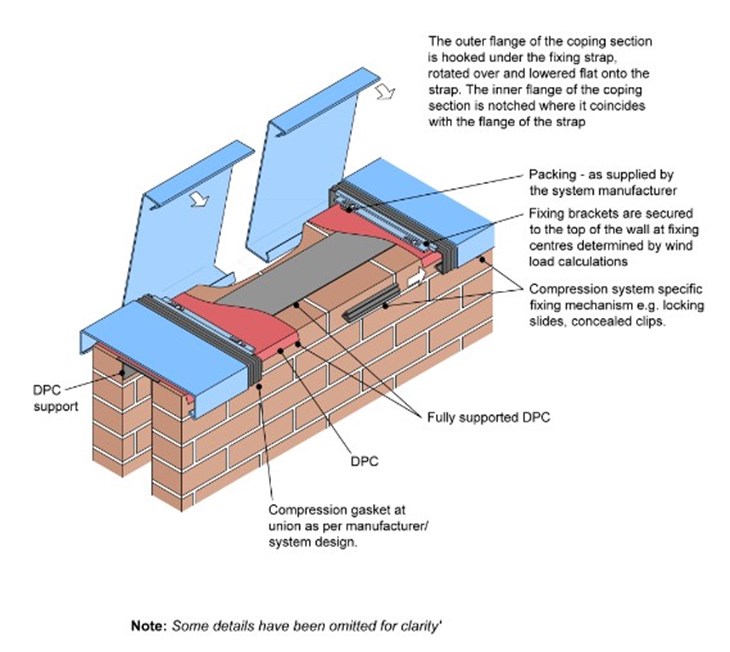
- Incorporate robust and durable joints, completed in strict accordance with the system manufacturers’ guidance. For the purpose of warranty provision, reliance on site applied sealants is not permitted.
Where gaskets are part of the system jointing, manufacturers must confirm the life expectancy of the gasket achieves a minimum 15-year durability period. Any maintenance of gaskets should be relayed within any ‘Operations & Maintenance Manual’ for the property, in order to ensure the required maintenance regime is met.
Where the specified system relies on overlapping sections or joints that utilise an anti-capillary methodology e.g. drainage gaps at joints, the developer must prove and demonstrate through testing that sufficient weather tightness can be achieved.
- Be secured to the wall. The preferred method is the use of concealed bracketry, fixings and gaskets which avoids the need for penetrations through the capping. Where this approach is not adopted e.g. where fixings are taken through the top or side of the capping, all fixing techniques used must prove and demonstrate to the Warranty surveyor that the risk of water penetration has been mitigated. For the purpose of warranty provision, reliance on site applied sealants is not permitted and system-specific, manufacturer-approved techniques must be used.
The pull-out resistance of the fixings must be checked for wind uplift by a suitably qualified engineer. Adhesive bonding of pressed metal copings alone is not considered acceptable for warranty purposes.
- Be designed to accommodate movement e.g. thermal expansion and contraction – notably at external and internal corners. Typically, aluminium requires an allowance of approximately 1mm per linear metre for movement.
- Achieve a minimum overlap of 75mm at any lead soaker, lead upstand or secret gutter location. Consideration must be given to bi-metallic corrosion occurring between the pressed metal work, lead work and associated fixings.
2.3 Defence line 2: The horizontal damp proof course (DPC)
The DPC is positioned directly below the coping provision. It is considered as the second line of defence against water penetration into the parapet wall, guarding the building fabric and any cavities below.
Directly beneath the coping, all parapet walls should be provided with a horizontal DPC which:
- Is formed via a single length of DPC as far as practicable. Where joints and laps are unavoidable, horizontal DPC must have a minimum 150mm lap (300mm lap is preferable) with the laps at corners formed to the full width of the wall it protects.
- Is appropriately sealed at overlaps in the material. Sealing of joints should be in accordance with the DPC manufacturers’ requirements. Typically, the bonding materials used to create the seal may be solvent contact adhesive or butyl rubber tapes.
- The horizontal DPC must be fully supported across any cavity in the structure below, for the continuous length of parapet.
Where masonry coping stones are being used, the DPC must:
- Be of suitable material specification. Typically bedding mortar and masonry coping stones are reliant on the bonds achieved with the DPC. Incorrect selection can adversely affect structural performance of the parapet wall e.g. increased risk of lateral shifting of masonry coping stones in service. Resultantly DPC materials attaining the correct bond performance should be specified and this should be checked against third party accreditation as suitable in situations of minimal load. (For further guidance on DPC selection, refer to BS 8215)
- Have a width that creates an overhang to the wall below. I.E. It should cover the full width of the wall, extending and terminating to a position at least 5mm beyond each face of the parapet wall.
- Be laid on a full bed of mortar onto the head of the parapet wall and support board using the same mortar specification used to bed the masonry coping stones. The coping stones must be immediately laid above the DPC in fresh mortar in order to maximize the bond between the coping and the wall beneath.
Where pressed metal copings are being used, the DPC must:
- Have a width that creates an overhang to the wall below. In other words, it should fully cover the full width of the wall, extending and terminating to a position at least 5mm beyond each face of the parapet wall.
- Be laid and secured in line with the guidance issued by the pressed metal coping system manufacturer.
In both instances, any penetrations through the horizontal DPC e.g. from coping stone fixings, balustrades, balcony guardings, must:
- Be fully sealed to prevent penetrating moisture, using working practices and suitably durable sealant material recognised by the manufacturer of the DPC system as acceptable and compatible. Manufactured DPC pre-formed cloaks are preferred where complex shapes are created by penetrations such as wind post penetrations.
OR
- Have a suitably lapped DPC arrangement, formed and fully sealed over penetrations.
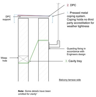
2.4 Defence line 3: The cavity tray
Within parapet walls, cavity trays are considered the final line of defence. Their function is to intercept, and divert any water entering the cavity to a suitable external face via weep holes.
A cavity tray must be incorporated into all designs incorporating a masonry outer leaf and must always must be positioned to prevent ingress of water into the roof structure. Where the external wall has cavity insulation installed, the cavity tray should always slope down towards the outer leaf.
Where the parapet is constructed in facing masonry, including rendered masonry, a DPC cavity tray must be provided at a height of not less than 150 mm above the top surface of the adjoining flat roof, which links directly with and laps over the flashing to the roofing to provide continuity.
Where the inside face of the parapet is entirely protected by the flat roofing membrane or cladding, a DPC cavity tray must be installed as close to the coping as practically possible, draining towards the outer leaf.
All cavity trays must:
- Be of suitable material specification. Materials attaining the correct bond performance should be specified and this should be checked against third party accreditation as suitable in situations of minimal load.
- Be continuously supported - for warranty purposes, the preferred method is to use proprietary self-supporting cavity tray systems to prevent potential water ingress through parapet walls due to poor installation of flexible cavity trays. Where a developer is unwilling to use proprietary cavity trays, evidence of how a flexible cavity tray are to be supported is required. (This guidance applies to both masonry and framed construction).
- Be securely fixed to maintain their position, achieving a minimum 150mm rise, measured vertically within the residual cavity. Where cavity tray material passes through any masonry leaf, it must be sandwiched between even beds of wet mortar, receiving at least one further course of masonry units on mortar to achieve the required bond. When securing to framed construction e.g. timber frame, surface fixing must be done in strict accordance with manufacturers guidance and materials e.g. bonding materials, fixing strips.
- Fixing to insulation boards alone must be avoided and the cavity tray will require to lap with any breather membrane on the frame construction.
- Be formed with minimal joints, as far as practicable. Where joints and laps are unavoidable, laps should be formed and fully sealed in accordance with the manufacturers’ guidance. For complex geometry e.g. internal and external corners, wind post obstructions, the use of pre-formed cloaks are recommended.
- Weep holes must be incorporated at a maximum 900mm centres.
2.5 Variations to the ‘3 Lines of Defence’
Where less than three lines of defence are proposed, these should only be accepted in exceptional circumstances on the basis that the following are in place:
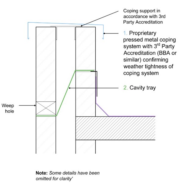
Situation A - 2 Lines of Defence
Where a pressed metal coping/jointing system is proposed with no horizontal DPC beneath or roofing membrane, then the coping/jointing system used must hold a valid third party accreditation (BBA or similar) which adequately demonstrates weather tightness and which is deemed acceptable to the warranty provider.
No reliance must be placed on silicone sealant in the coping system in any situation.
A cavity tray is still required to be installed in this instance. The third party accreditation must be carefully reviewed by the architect, developer and installer in order to demonstrate to the warranty surveyor that all conditions and details within the certificate are appropriately satisfied.
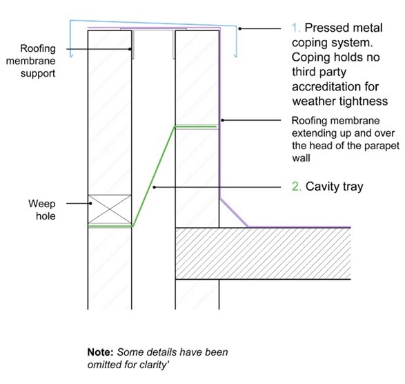
Situation B - 2 Lines of Defence
Where the roofing membrane is to extend up and over the head of the parapet wall and be covered by a pressed metal coping, the fixings will penetrate the roofing membrane. As a result, penetrations should be appropriately sealed as per the membrane manufacturer’s guidance. A cavity tray is still required.
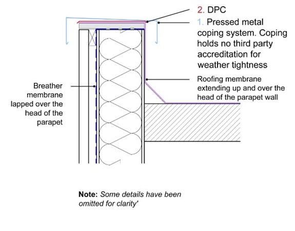
Situation C – 2 Lines of Defence
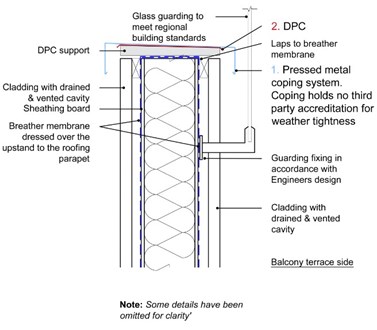
In framed construction, where cladding forms the outer surface of the wall and the roofing membrane is to extend up and over the head of the parapet which will then be covered by a pressed metal coping:
- DPC is required to be placed beneath the coping.
- In addition the breather membrane must also extend over the head of the parapet wall.
- The copings must adequately lap over the top of the cladding.
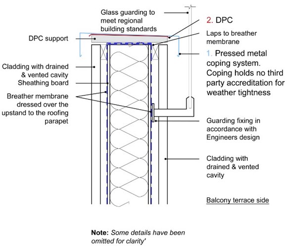
Situation D. 2 Lines of Defence.
Where framed construction is used and either side of the parapet wall is to be clad, which incorporates a drained and vented cladding:
In this situation:
- A correctly weathered coping and correctly installed horizontal DPC must be installed.
In addition the breather membranes from each side of the frame, must also extend over the head of the parapet wall.
2.6 Additional considerations for terrace guarding and balustrade systems
The constituent parts of the ‘3 lines of defence’ principle are only as strong as their weakest detail.
The penetrations created by structural connections and fixings into and through various layers of the parapet wall carry significant risks of water penetration.
Resultantly, the design for the guarding must be identified at an early stage and appraised to ensure the weather tightness of the parapet construction is protected and that all lines of defence are present and not compromised by fixings or other aspects of the design.
Examples of some typical approaches are provided alongside the guidance below:
- Any guarding should ideally be mounted to the sides of the parapets, either internally or externally via face fixings into the parapet wall and not through the coping. This should be the preferred method as it prevents creating weak spots for water ingress.
- The copings weathered upper surface, projection and drainage function must be uninterrupted and unhindered by guarding provisions e.g. glazing channels which are recessed into and divide coping provisions should be avoided.
- Where this cannot be avoided, and any guarding over a coping arrangement is in continuous contact, the free drainage of the coping should not be impeded. In such instances, coping arrangements must incorporate a fall away from the obstruction to any outside edge.
- Where the guarding incorporates proprietary glazing and framing profiles, drainage provisions from glazing channels must be provided and kept free from obstruction. Particular attention should be paid to sealant pointing used where such profiles are in continuous contact with the upper surface of a coping system, as this area can often restrict drainage when incorrectly executed.
- Where the guarding, over a coping arrangement, is in continuous contact with the coping fixings which penetrate the coping arrangement, the fixings must only pass through a self-sealing butyl tape. Reliance on silicone is not acceptable.
Guarding incorporating elements of glazing may need to be heat soak tested to BS EN 14179-1.
Section 3 - Raking parapets to masonry and framed structure
3.1 Identifying and investigating failures
In the event of water ingress through raking parapets, invasive investigations often reveal failings in the detailing and overall execution of these critical areas of construction.
Commonly occurring issues are highlighted below, categorised under their position in the ‘3 lines of defence’ principle.
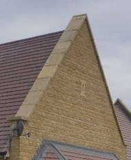
Images depict a raking parapet with stone copings. Various failings of the 3 lines of defence are present such as a horizontal DPC of incorrect width which lacks support across the cavity, a lack of mortar bedding across the full width of the wall and missing mechanical fixings leading detachment of the coping, and the omission of the cavity tray.
3.2 The ‘3 Lines of Defence’ principle in raking parapets
When considering the raking parapet wall, we are faced with a structure that is as equally exposed to the effects of weather as its horizontal counterpart, but with the added complication of constructing to a slope.
The 3 lines of defence principle highlights 3 distinct areas of focus in a parapet wall construction:
- Raking Coping/Capping - A correctly installed, weathered coping or capping with robust weatherproof connections.
- Raking Horizontal DPC - A fully supported DPC, with sealed joints at laps, intersections and any penetrations.
- Stepped Cavity Tray - A correctly installed stepped cavity tray, with sealed joints at laps, complete with weep holes.
This guidance document provides a detailed insight on our technical requirements for the ‘3 Lines of Defence’ principle which must be incorporated into parapet design.
3.3. Defence line 1: The raking coping or capping
Firstly, a raking coping is a construction that protects the top of a wall, or parapet and sheds rainwater clear of the surfaces beneath. Additionally, as raking structures are set to slope, any rainwater will also move downwards on the slope.
Copings can be formed using masonry or pressed metal profiles.
In some instances, a raking capping may also be used. These capping sections protect the top of a wall from water ingress but do not project beyond the walls outer surface and therefore can lead to staining of the wall beneath.
Capping arrangements are typically formed from pressed metal profiles.
All raking parapet walls should be provided with a suitable coping or capping construction, which:
- Is capable of shedding water – where a coping is provided, a minimum 2 degrees fall from horizontal is required at the top surface of a coping. A coping without a fall is not permitted.
- Creates an overhang on the face of the wall beneath – for a coping, a minimum of 40mm on each side must be achieved.
- Incorporates a throating or drip provision.
- Has a robust and durable jointing procedure.
- Must have a full fixing design carried out by a suitably qualified professional e.g. a chartered structural engineer. The design should be site specific in relation to exposure of the site, and be specific to the type of coping or capping being installed in relation to the structure below e.g. the gradient (slope/pitch), the substrate beneath the copings e.g. solid masonry, frogged or perforated facing bricks, etc.
- Incorporates weather tight detailing to junctions with other elements of structure e.g. where a coping or capping abuts a cavity wall, a suitable flashing and proprietary cavity tray with stop ends and weep holes must be provided.
Where masonry coping units are being used, they must:
- Be frost resistant.
- Be bedded and pointed using an appropriate high durability mortar, subject to the supporting masonry type – see Appendix C1 of the Technical Manual. The mortar specification will be dependent upon the type of masonry unit being walled.
- Include anti capillary or drip grooves to their underside – typically set back 10-15mm from the outer edge, and typically sized at 12mm wide x 8mm deep.
- Include a suitably designed mechanically fixed restraint mechanism to secure the raking masonry copings to the wall beneath. Any fixing provision should be stainless steel e.g. fixings, dowels and bracketry. Exposed conditions e.g. coastal locations, require all fixings are specified A4 grade.
- Transfer any construction or movement joint in the supporting structure below, through the masonry coping stone. Any horizontal DPC and cavity tray arrangement must be continuous at the movement joint. In addition, the coping stone manufacturer’s requirements for the provision of movement of the coping itself (e.g. thermal expansion) must also be met.
- Be sealed with a sealant that is able to accommodate the movement that may occur. Any sealants must be selected according to ‘BS 6213 Selection of Construction Sealants: Guide’. It is the role of the building designer to specify the sealant to be used.
Where the coping stone is porous, manufacturers may recommend a proprietary sealant is applied to the coping, this may include a primer. The coping stone manufacturers’ advice should be sought in such instances.
- Not be used in conjunction with timber frame/SIP construction due to concerns over maintaining weather tightness and allowance for differential settlement in the timber frame.
Where pressed metal coping or capping units are being used, they must:
- Be suitably durable for the exposure conditions on site and will achieve a minimum 15-year durability, inclusive of fixing elements e.g. screws, cleats, fixing bracketry.
Bi-metallic corrosion must be considered between the fixing and any pressed metal system. Consideration must be given to any aggressive environment affecting the site e.g. coastal locations, industrial zones, etc.
Aluminium coping or capping systems must not be installed in contact with copper or its alloys, or the runoff from them – notably, attention should be given to the effect of any lightning conducting fittings attached to or in proximity to pressed metal copings.
Aluminium copings and capping systems should not be bedded into mortar or concrete.
- Incorporate pre-formed drip provision within their profile.
- Incorporate robust and durable joints, completed in strict accordance with the system manufacturers’ guidance. For the purpose of warranty provision, reliance on site applied sealants is not permitted.
Where gaskets are part of the system jointing, manufacturers must confirm the life expectancy of the gasket achieves a minimum 15 year durability period. Any maintenance of gaskets should be relayed within any ‘Operations & Maintenance Manual’ for the property, in order to ensure the required maintenance regime is met.
Where the specified system relies on overlapping sections or joints that utilise an anti-capillary methodology e.g. drainage gaps at joints, the developer must prove and demonstrate through testing that sufficient weather tightness can be achieved.
- Be secured to the wall. The preferred method is the use of concealed bracketry, fixings and gaskets which avoids the need for penetrations through the coping. Where this approach is not adopted e.g. where fixings are taken through the top or side of the coping, all fixing techniques used must prove and demonstrate to the warranty surveyor that the risk of water penetration has been mitigated. For the purpose of warranty provision, reliance on site applied sealants is not permitted and system specific, manufacturer approved techniques must be used.
The pull-out resistance of the fixings must be checked for wind uplift by a suitably qualified engineer. Adhesive bonding of pressed metal copings alone is not considered acceptable for warranty purposes.
- Be designed to accommodate movement e.g. thermal expansion and contraction – notably at external and internal corners. Typically, aluminium requires an allowance of approximately 1mm per linear metre for movement.
- Achieve a minimum overlap of 75mm at any lead soaker, lead upstand or secret gutter location. Consideration must be given to bi-metallic corrosion occurring between the pressed metal work, lead work and associated fixings.
3.4 Defence line 2: The raking DPC
The raking DPC is positioned directly below the coping provision. It is considered as the second line of defence against water penetration into the raking parapet wall, guarding the building fabric and any cavities below.
Directly beneath the coping, all raking parapet walls should be provided with a horizontal DPC which:
- Is formed via a single length of DPC on each rake. For the purpose of warranty provision, joints in the DPC are not permitted on raking parapets. Where dual pitched roofs are encountered, an allowable overlap will occur at the transfer from one plane to another e.g. the ridge. This exception must have a minimum 150mm sealed overlap (300mm lap is preferable).
- Is appropriately sealed at overlaps in the material. Sealing of joints should be in accordance with the DPC manufacturers requirements. Typically, the bonding materials used to create the seal may be solvent contact adhesive or butyl rubber tapes.
- The horizontal DPC must be fully supported across any cavity in the structure below, for the continuous length of parapet.
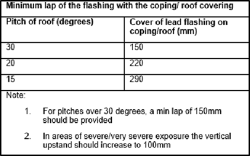
- Where the wall upstand above the roof line is relatively short e.g. 150-300mm, any lead flashings used the weatherproof the junction must dress underneath the DPC arrangement and be secured in place prior to the horizontal DPC installation. The lead flashing must sit on the horizontal portion of the wall by 25-30mm.
As an alternative to a DPC material being used, a lead detail could be adopted. In such a cases installation must be in accordance with the ‘Rolled Lead Sheet guidance’ and the guidance within Section 11 of the Technical Manual with regards the execution of flashing details.
Where masonry coping stones are being used, the DPC must:
- Be of suitable material specification. Typically bedding mortar and masonry coping stones are reliant on the bonds achieved with the DPC. Incorrect selection can adversely affect structural performance of the parapet wall e.g. increased risk of lateral shifting of masonry coping stones in service. Resultantly DPC materials attaining the correct bond performance should be specified and this should be checked against third party accreditation as suitable in situations of minimal load. (For further guidance on DPC selection, refer to BS 8215)
- Have a width that creates an overhang to the wall below. It should fully cover the full width of the wall, extending and terminating to a position at least 5mm beyond each face of the parapet wall.
- Be laid on a full bed of mortar onto the head of the parapet wall and support board using the same mortar specification used to bed the masonry coping stones. The coping stones must be immediately laid above the DPC in fresh mortar in order to maximize the bond between the coping and the wall beneath.
Where pressed metal copings or capping sections are being used, the DPC must:
- Have a width that creates an overhang to the wall below. It should fully cover the full width of the wall, extending and terminates to a position at least 5mm beyond each face of the parapet wall.
- Be laid and secured in line with the guidance issued by the pressed metal coping and capping system manufacturer.
- Hold a valid third party accreditation where horizontal DPCs do not form part of the installation. This documentation must prove and demonstrate weather tightness of the installed system to a point deemed acceptable to the warranty provider.
In both instances, any penetrations through the horizontal DPC e.g. from coping and capping sections must:
- Be fully sealed to prevent penetrating moisture, using working practices and sealant material recognised by the manufacturer of the DPC system as suitable. This practice must prove and demonstrate weather tightness of the installed system to a point deemed acceptable to the warranty provider.
3.5 Defence line 3: The stepped cavity tray
Within parapet walls, cavity trays are considered the final line of defence. Their function is to intercept, and divert any water entering the cavity out of the fabric to a suitable external face via weep holes.
Where the external wall has cavity insulation that terminates at a horizontal axis e.g. coincidental to the insulation within an adjacent cold pitched roof, then a horizontal cavity tray will be located directly above the insulation and should slope down towards the outer leaf.
Where the external wall has insulation to the full height e.g. where the roof structure contains habitable space, then a stepped cavity tray must be incorporated into all designs. Where the parapet is constructed in facing masonry, including rendered masonry, a DPC cavity tray must be provided at a height of not less than 150 mm above the top surface of the pitch roof, which links directly with and laps over the flashing to the roofing to provide continuity.
Where the inside face of the parapet is entirely protected e.g. encapsulated in lead, a DPC cavity tray must be installed as close to the coping as practically possible, draining towards the outer leaf.
All stepped cavity trays must:
- Be of suitable material specification. Materials attaining the correct bond performance should be specified and this should be checked against third party accreditation as suitable in situations of minimal load.
- Be continuously supported - for warranty purposes, the preferred method is to use proprietary self-supporting cavity tray systems to prevent potential water ingress through parapet walls due to poor installation of flexible cavity trays. Where a developer is unwilling to use proprietary cavity trays, evidence of how a flexible cavity tray are to be supported is required (this guidance applies to both masonry and framed construction).
- Be securely fixed to maintain their position, achieving a minimum 150mm rise, measured vertically within the residual cavity. Where cavity tray material passes through any masonry leaf, it must be sandwiched between even beds of wet mortar, receiving at least one further course of masonry units on mortar to achieve the required bond. When securing to framed construction e.g. timber frame, surface fixing must be done in strict accordance with manufacturers guidance and materials e.g. bonding materials, fixing strips.
- Be formed with minimal joints, as far as practicable. Where joints and laps are unavoidable, laps should be formed and fully sealed in accordance with the manufacturers’ guidance.
- Weep holes must be incorporated at a maximum 900mm centres.
- Further guidance on acceptable execution of stepped cavity trays – refer to Section 6 of the Technical Manual.
Section 4 – workmanship and quality assurance
As ever workmanship is key and the developer must demonstrate to the warranty surveyor the ‘Quality Assurance’ (QA) procedures for the installation of the copings, DPC’s and cavity trays to the parapets.
The QA procedure must prove and demonstrate the attainment of weather tightness and durability of the construction ensuring that the parapet arrangement represents a standard insurance risk. As the warranty surveyor will not be able see every parapet being completed the site manager should keep a detailed set of photographs at key risk stages (before and after each defence line stage for example) and these would need to be provided to the warranty surveyor. This should be discussed with the warranty surveyor before works on the parapets begin.
Warranty position
In order to reduce claims on parapet wall constructions, it is of paramount importance that all aspects of the parapet detailing are discussed at the ‘Site Risk Assessment’ stage, to ensure the design incorporates the lines of defence we require.
This article may not cover every situation you are likely to encounter on a site, however for each situation you encounter, please ensure as many of the lines of defence as discussed in this article, are incorporated into the design and correctly constructed, in order to reduce the potential of a claim occurring.
Should you have any further questions, please speak to your LABC Warranty risk management surveyor or your Local Authority Building Control inspector.
