
Causes of Underfloor Heating Failure
In most cases failures are attributable to one of the following:
- Failure to consider the floor layout at an early stage.
- Failure to consider the floor finish at an early stage.
- Incorrect installation of UFH system or screed.
- Insufficient screed drying time.
- Incorrect screed mix.
- Excessive moisture in the screed.
- Movement in the floor structure.
- Incorrect commissioning or design of under floor heating systems.
UFH System Design and Installation
Layout of UF heating loops
The layout of the underfloor heating loops should take into account installations that involve penetrating the floors. The underfloor heating design should be provided by the first fix stage.
Maximum temperature of the floor surface
BS EN1264-2[1] limits the maximum temperature of the floor surface to 29°C, or 27°C where floor tiling is proposed.
It is important that installations should be designed and specified as an integrated package by the system manufacturer to ensure compatibility of all the components.
BS8203 Code of Practice for the Installation of Resilient Floor coverings states: When used with many flooring materials underfloor heating can cause problems if the temperature at the interface between the subfloor and flooring exceeds 27°C, or is subject to rapid fluctuations in temperature.
Where a resilient floor covering is proposed: ‘the temperature should never exceed the agreed maximum of 27°C at the underside of the floor covering (the adhesive line). Note: UFH designers may refer to this as the ‘interface’ temperature.
Primary pipework
The pipework which supplies hot water from the main heat source to the Domestic hot water (DHW) cylinder, the radiators and underfloor heating system manifolds is the primary pipework. Building Regulations guidance requires that only the primary pipework to the DHW cylinder is insulated. Best practice, however, would be to insulate all primary pipework. Heat losses from the underfloor heating manifolds can also contribute to system inefficiencies. Methods of addressing this include insulating the manifolds or placing them inside an insulated enclosure.
Manifold assemblies
Manifold assemblies normally consist of a number of ports, each port connected to one underfloor heating loop. Temperature control can be achieved to each individual room as each room is generally served by its own port on the manifold. It is essential that manifolds can be commissioned to set the correct flow through each circuit.
Location of manifolds
Manifolds should be located centrally within the home to facilitate a simple layout of pipework loops and be located to enable easy access.
Labelling
Correct labelling should be provided to enable effective inspection, commissioning, maintenance and repairs of the underfloor heating installation.
Maintaining water flow
Any sharp bends in pipework loops leading to and from the manifolds should be avoided as they could restrict the free flow of water. Where 90° bends are necessary a metal former should be used.
Preventing leaks
For ease of maintenance and repair, all joints between the manifold and pipework loops should be accommodated above the level of screed. Joints should never be embedded in the screed.
Secure fixing
In order to ensure that any bends in the pipework loops are not too sharp, manifolds should be located at an appropriate height above the floor and must be securely fastened to the wall.
Installing underfloor heating
Underfloor heating loops should not be installed until all external doors and windows have been installed and the property is water tight, ensuring that the installation is protected from damage due to frost in the pipework loops during cold weather.
Layout of pipework loops
BS EN 1264 provides guidance on the design and sizing of the system. The spacing of the pipework should be even but locally may be reduced around the external perimeter of rooms to compensate for the additional heat loss that occurs here. To prevent heat losses from the floor to the walls edge insulation of the floor is required.
Layout
The most appropriate layout for a particular application should be confirmed by the system manufacturer. Underfloor heating pipework loops can be laid out in several patterns, depending on the fixing methods and shape of the room.
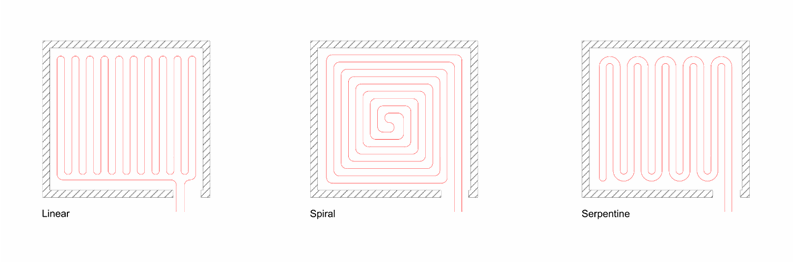
Pipework loops should not extend right to the edge of the floors and under the skirting boards.
Insulating the floor
To minimise downward heat losses from the underfloor heating installation, floors should be insulated.
Ground floors
The insulation type and thickness should be confirmed by calculations, to comply with the relevant regional building regulations taking into account the specific shape and size of the floor.
Intermediate floors
Although Building Regulations do not normally require intermediate floors within homes to be insulated to prevent heat loss, where underfloor heating is installed, insulation will need to be incorporated to direct heat flow upwards.
Floor finishes above underfloor heating
To ensure adequate heat output the UFH system must be designed to allow for the proposed floor finishes.
- Stone and ceramic tile finishes are at risk of developing cracks from screeds drying out or as the underfloor heating pipes expand and contract. To counter this an appropriate decoupling membrane can be used.
- Due to thermal expansion and contraction natural timbers are prone to cracking when used over underfloor heating installations and care should be taken when specifying board width and thickness.
- Engineered hardwood boards expand and contract less than solid timber boards which means they are less prone to damage.
- The use of felt or polyurethane underlays under carpets should be avoided.
- Laminates and synthetic vinyl work well with underfloor heating due to their generally lower thermal resistance than carpets.
Testing the installation
Once the underfloor heating loops have been laid, the installation should be pressure tested. To meet the requirements set out in BS EN 1264-4[4] this should be at two times the working pressure. Although BS EN 1264-4[4] requires testing at a minimum pressure of 6 bar, underfloor heating suppliers generally recommend testing up to twice this pressure, maintained for 24 hours. Pressure testing should be carried out prior to the screed being installed, so that remedial works can be carried out without causing disruption.
Screed Design and Installation
Screed Type
Screeds tend to be either semi-dry formula which is hand applied and then trowelled to a finish or liquid, free-flowing mixture that is pumped to the position and to a prescribed depth.
Of these there are:
- Modified Semi-Dry Cementitious
- Modified Self-Levelling Cementitious
- Modified Self-Levelling Non Cementitious
- Anhydrite
- Wearing Granolithic
The ratio of water added to the self-levelling screed powder is critical as too much will result in cracking occurring.
Self-levelling screeds, if correctly applied, will have a quicker drying / curing time than traditional screeds.
Most screeds are applied as floating screeds as this is most practical for placing on top of underfloor heating and insulation solutions. The screed is put on top of a separating membrane which will be applied on top of the layer of underfloor heating. This method requires a minimum of 75mm coverage otherwise cracking will occur.
Key steps to prevent floor screed issues
- Substrates must be level with no pockets or high spots to ensure the thickness of the screed remains even
- The insulation must be tightly butted together and level
- Screeds must be correctly mixed
- Screeds must not be walked on during the drying period
- Must not be constructed during cold periods (below 5°C)
- Movement joints will be required
- Movement joints also required if Bay sizes exceed 40m2
- The screed must be ready to accept any Floor tiling
- Drying times:
- With cementitious levelling screeds, one day should be allowed for each millimetre of thickness for the first 50 mm, followed by an increasing time for each millimetre above this thickness (BS 8204)
- Polymer modified screeds: strictly follow the manufacturer’s specifications and recommendations
- The drying time allowed must be calculated for the proposed depth of screed, taking account of the environmental conditions present e.g. Temperature and humidity
- Drying times for polymer modified screeds could potentially be different to cementitious screeds
- All subcontractors involved with the screed and floor finishes (including installation of underfloor heating systems) must follow the installation requirements and not deviate or change materials
- The screed should not be walked on until fully cured
- Surface finishes placed on a screed too early will fail
Note: The moisture contents of levelling screeds onto which particular floorings are to be laid and methods for measuring moisture content are given in BS 5325, BS 8201, BS 8203 and BS 8425.
- Provision of Edge strip perimeter expansion joint – tile level
- UFH System testing and commissioning
- Moisture testing of the screed where floor tiling is proposed
- Screed preparation for finishes
- Application of the adhesive using double gluing technique
- Full contact of the tile and adhesive
- Adhering to the manufactures process during the installation of the flooring
- End user information
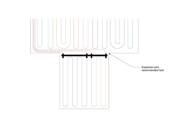
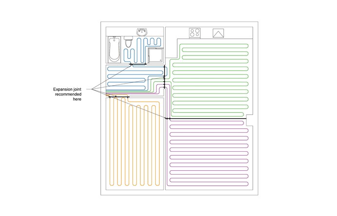
Provision of Movement Joints in the floor screed or tiles
Movement joints should be provided:
- Across door thresholds
- Where bay sizes exceed 40m2 with a maximum of 8m on any one side
- Where sub floor construction joints exist or change of span occurs e.g. beam and block floors
- Between independently controlled heating zones
- Between heated and unheated areas of screed
- Additional joints should be considered in areas of high thermal gain e.g. large conservatories or glass atria
Construction of Movement joints
- Bay joints should be formed using rigid joint formers where possible, which can be placed during the preparation phase and will remain in place during operation. Ideally the joint former should be 5mm lower than the finished screed depth to allow a smooth transition in height between bays
- All joints in the screed should reflect through to any subsequent bonded floor covering
- Joint positions should be specified prior to the installation of the screed and full consultation between all parties including the main contractor, underfloor heating installer, finished flooring installer and the screed installer should take place to determine appropriate locations
- Movement joints should be carried through the subfloor to the floor finish and all applied layers terminated either side of the joint
- The joint should be filled with a suitable flexible filler and a proprietary cover strip applied to cover the joint. Grout must not be used
- They should not be bridged by any resilient, textile or other adhered floor finish
- Movement joint covers may be flush, surface mounted or bedded in mortar and metal, metal with a rubber insert or PVC
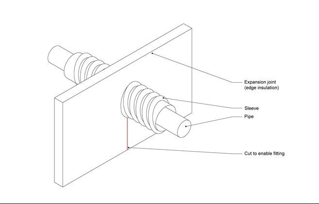
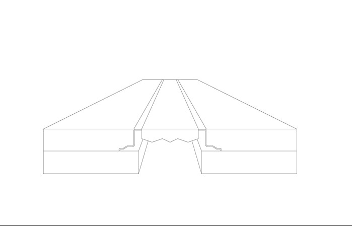
Underfloor Heating Pipe Passing Through Expansion Joint
Typical Expansion Joint Cover
Provision of Edge strip perimeter expansion joint
When incorporating under floor heating:
- Screeds should be isolated at all edges, abutments and columns to allow for movement due to thermal loadings
- The manufacturers’ guidance for both the floor screed and the tiling must be followed to determine the minimum thickness of edge strip required to allow for expansion. This will typically be between 6-15mm
- The joint can be concealed by the skirting
- These joints must be left empty, or else filled with a compressible material
- Never apply grout in movement joints
Underfloor heating (UFH) Testing and Commissioning
- UFH systems should be commissioned before floor finish is applied. This will add to the total time before any floor finish can be applied. Note: If floor finishes are installed prior to the UFH being turned on and commissioned any residual moisture in the floor is driven to the surface of the screed and can potentially cause delamination of the floor finish
- Pressure testing of the system does not constitute commissioning of the system. The heat source has to be in place and operating in order to deliver the correct temperatures
- The UFH system must be commissioned in accordance with the manufacturer’s recommendations by their approved installers. A commissioning certificate will be required
Moisture testing of the Screed where floor tiling is proposed
- Moisture testing should be carried out after the commissioning of the UFH system, but before any tiles are laid
- Moisture testing is carried out using a suitable approved method such as a flooring hygrometer or carbide bomb test. Due to the potential inaccuracies of using hygrometers at high humidity levels, a direct measurement should be used such as carbide bomb or oven dried sample
- The base is deemed to be sufficiently dry when the relative humidity, as measured by a surface mounted flooring hygrometer/probe is 75% RH or less. For the use of a flooring hygrometer reference should be made to Dampness testing in BS5325, BS8203, BS8425 and BS8201
- The UFH system heating must be switched off 96 hours prior to any hygrometer test being carried out
- The hygrometer must be allowed to remain in position until full equilibrium has been established. This is generally considered to be 72 hours but could be longer over thick sections and considerably longer on power floated concrete
Screed Preparation for finishes
- The top surface of screeds may need to be scored, sanded or keyed in preparation to accept the primer and floor tiling adhesive
- Sanding, keying etc. of the screed surface allows the penetration of primers. It also provides a “key” for the adhesive to grip onto
- The surface must then be cleared of dirt and debris prior to primers being applied
- Any primers and adhesives must not be applied until the screed has fully hardened and dried out. Drying times vary depending on the type of screed
- Surfaces to be tiled should be rigid, dimensionally stable, flat with no dips and rises, sound, clean and free from laitance, paints, salts, grease, dust and any contamination which may prevent adhesion
Application of the flex adhesive using double gluing technique
Tile fixing should be carried out in accordance with BS 5385 and BS 8000 Codes of Practice for the installation of wall and floor tiles.
- The tiling manufacturer’s specifications for fixing should be followed. g. Travertine tiles may require double gluing. Large sized tiles may also require this fixing method
- Double gluing (applying adhesive to the underside of the tile and also the substrate) may be necessary
- The adhesive must be used to the manufacturer’s recommendations
- The adhesive will need to be compressed by the tile to ensure full adhesion
- Large voids must be avoided when fixing tiles
- Floors should not be opened to traffic until the adhesive has hardened
Full contact of the tile and adhesive
- The adhesive will need to be compressed by the tile to ensure full adhesion and solid bedding without creating voids
- Thin-bed method with adhesive and notched trowel: Verify that there is full contact between the adhesive and the tile base
Adhering to the manufacturers’ process during the installation of the flooring
All the relevant manufacturers recommendations should be followed which will identify timelines to adhere i.e.:
- Removing the laitance by sanding to provide a key for the primer and/or adhesive
- Commissioning the underfloor heating before tiling commenced
- Allowing the UFH system to cool down for at least 48 hours before tiling commences
- Moisture testing to confirm the dryness of the screed before tiling commenced
- Ensuring the time from screed completion to tiling commencement is calculated and adhered to
- Ensure the tiling adhesive is allowed to set before the tiling is walked on (Typically 12 -24 hours dependant on environment conditions)
- Ensure the UFH system is not turned on for at least 48 hours after the tiling is completed
Handover of the UFH System
Building Regulations require information to be provided to residents to enable them to use the systems installed in their homes effectively. This should include:
- Manufacturers’ manuals for products
- Heating zones: Clear floor plan drawings showing how the property is split into control zones should be included
- Programmers and thermostats: Information and operational guidance should be provided for the control interface
- Characteristics of system: It is important for residents to understand the key differences between UFH systems and more traditional heating systems. While the floor might not feel warm the system may be operating at its optimum setting. Where the UFH system is embedded in the screed there will always be a time lag between the UFH system coming on and the room temperature increasing. It is important to communicate the implications of this to residents
