Introduction
A blue roof is a flat roof or podium deck which is designed to provide controlled attenuation and management of rainfall to the sewer or outfall system, as part of a Sustainable Urban Drainage System (SuDS) proposal. This is particularly relevant on developments located in dense urban environments.
This guidance provides information to designers, developers and surveyors to assist in meeting the Functional Requirements of the Technical Manual where a blue roof is proposed on a project covered by our warranty.
Contents
This document includes:
- Definition of a blue roof (for warranty purpose)
- Design considerations
- Design requirements
- Installation and testing requirements
- Operations and maintenance
- Blue roof layering – detailing
- References and further guidance
Definition
The requirement of any ‘roof’ or podium deck that is to be waterproofed, is to protect the structure and space beneath from the ingress of water.
A blue roof is defined as:
A roof design that is explicitly intended to store rainfall temporarily at a level not exceeding the designed hydraulic head, for a defined period of time above a thermally conditioned space.
A blue podium deck is defined as:
A deck design that is explicitly intended to store rainfall temporarily at a level not exceeding the designed hydraulic head, for a defined period of time above a thermally unconditioned space.
Blue roof systems manage rainfall by temporarily attenuating rainfall at a controlled predetermined rate and capacity before discharging into the wider drainage network / sewers. Blue roofs may be classified as either ‘Active’ or ‘Passive’ depending on the types of control devices used to regulate drainage of water from the roof and overflows. Active or ‘smart’ approaches are discouraged due to reliance on technological infrastructure and are reviewed on a case by case basis. They should only be proposed where it is not possible to specify a passive approach.
Design considerations
Scope of application
- All other retention, attenuation and ‘within-site’ surface water release strategies should have been explored, before a blue roof is considered.
- The use of space on the roof or deck surface – ‘the amenity space’ must be identified.
- The design of site drainage controls may be determined by flood risk strategies in planning consents with run-off rates typically in the range 5-10 l/s/hectare.
- Provisions for positive falls – falls not less than 1:80. Provisions for zero-falls — falls between 0 and 1:80*.
It should be noted that the degree of fall on a roof is absolutely critical to the functionality of a blue roof and warm blue roofs tapered or laid to fall have several beneficial advantages such as the avoidance of flotation risk and the removal of standing water.
However, the designer should note a positive fall will increase water depths on the roof, and lead to an uneven loading on the slab as water is stored in the tapering storage zone a fall creates which must be considered in the structural design approach for the slab.
Great care must be taken on long roofs with a slope to ensure that the fall is adequately designed into the storage, and that water depths at the downstream end are not excessive, either in terms of the vertical or horizontal loading.
Where a blue roof system is proposed above an unheated space these would be considered a podium deck. The designer should ensure that the deck is able to be sufficiently drained to limit ponding and backfalls.
Performance required
To satisfy our warranty requirements:
- All aspects of the design are to conform to BS 6229 and Section 11: Roofs of the LABC Warranty Technical Manual.
- Blue roofs should half empty in no more than a 12-hour period from the end of the specified design storm, AND should manage water for no more than a 24-hour period from the end of a 1:100 year storm profile for the roof (+40% minimum factor for climate change).
- There must be a concealed void to contain the designed attenuation capacity of storm water.
- Rainfall at the exposed surface level must be managed to ensure that it does not accumulate or pond water on the final finishes.
- There must be a multidirectional flow path above the waterproofing membrane, for water to reach the drainage points.
- All component materials and products used for a blue roof system must include a recognised third party accreditation certification or other harmonised European Standard.
- Flotation risk for inverted roofs should be calculated and addressed by providing loading to the insulation such that it cannot become buoyant. A warm roof to falls is encouraged to avoid the risks associated with flotation in an inverted warm blue roof.
Design intent
The design for a blue roof on a roof or deck slab must demonstrate:
- A satisfactory level of structural performance for the surface finishes.
- Applied loadings to the roof or deck slab including saturated material loads.
- Management of surface water into the attenuation layer.
- A controlled drainage discharge from the roof or deck slab.
- Architectural detailing to prevent water ingress at abutments, thresholds and joints.
- How will water be managed around potential landscaped features installed on the roof or deck, such as planters.
- A clear indication of the surface usage.
- Its possible future use.
- Thermal performance of space below in particular to an Inverted roof construction proposal.
- Meet the warranty Functional Requirement: the roof coverings shall be designed and constructed so they have an intended life of not less than 15 years.
Technical standards
For the design of a blue roof, reference to other associated technical standards may be appropriate.
Examples include:
- Continuous membrane roofing.
- Green roofs.
- Podium decks.
- Drainage
Waterproofing design
If the space beneath the blue roof is situated below ground level, the design may be required to be coordinated alongside a CSSW qualified structural waterproofing specialist.
Associated design principles
The principles of BS6229:2018 Flat roofs with continuously supported flexible waterproof coverings - Code of practice: are to be applied to waterproofing of roof and deck slabs to ensure water ingress does not occur.
BS 8102:2009 – Code of practice for protection of below ground structures against water from the ground are to be applied to ensure continuity of waterproofing at junctions with below ground construction.
Limitations of this guidance
For warranty purpose, where insulation is required, ‘cold deck’ applications are not an acceptable approach in any circumstance in the design of above ground attenuation surfaces such as blue roofs.
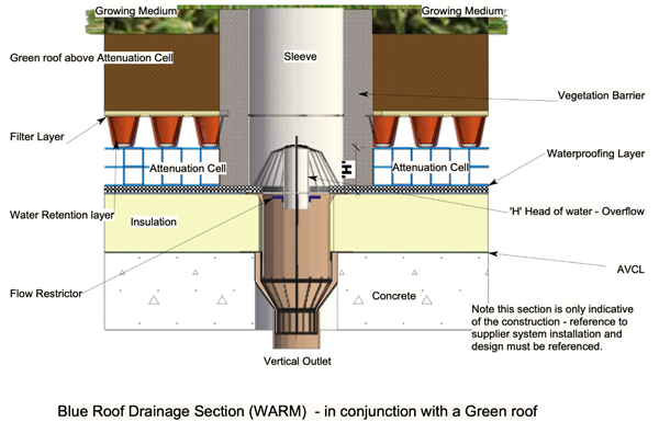
Blue roofs used in conjunction with green roof finishes can be effective. In these situations, the green roof build-up may be useable as part of the attenuation storage. However, the attenuated water must not exceed the designed water head.
Loadings applied must be checked and approved by the structural engineer for the design and deflected form of the roof or podium slab.
Attenuation cells have commonly a water head not exceeding 100mm (1.0KN.m-2). (Note: 60mm of water is approximately equivalent to the minimum imposed snow load of 0.6 KN .m-2 ). Total loading for the design of the reinforced concrete roof or deck must be checked and approved by the project structural engineer.
Inverted blue roofs where water storage is layered above the insulation and the waterproofing, will have to withstand potential buoyancy up thrust. This may restrict the depth of insulation which can be used as, a ballast weight of 1.0kN.m2 is required for every 100mm thickness of insulation (in addition to the water loading).
Inverted insulated roofs will require additional insulation to satisfy Building Regulation requirements through reduction of thermal performance of the insulation due to saturation and the cooling effect of water at the waterproofing layer.
This guidance is not intended as a standalone design guide and does not include full details of what must be considered to comply with other associated design guides.
Design requirements
• All proposals for above ground blue roof attenuation surfaces are considered on a case by case basis due to the developing nature of guidance available. See References and Further Guidance.
Design Information Submission Pack’ required
For warranty purposes, developers must provide information at the earliest opportunity and it should be noted only installers with a demonstrable history of installing blue roof systems are to be permitted.
A full design submission must include:- 1. Written demonstration that all other retention and within-site attenuation and release strategies have been explored before a blue roof has been proposed.
- 2. A full set of section details detailing each proposed build up for the above ground attenuation layers and blue roof areas and junctions with adjoining structures. Including:
- a. GA Plan Details for each above ground attenuation surface areas, noting build up types if these vary.
- b. GA plans and detail sections must show locations of movement Joints proposed.
- c. Details of large obstructions such as planters, M&E equipment or similar and method to ensure water is diverted around these obstructions where applicable.
- 3. Full details of component products used, including details of third party accreditation certification for all components of the all elements of complete proposed waterproofing and drainage system.
- 4. Structural engineers design philosophy statement including but not limited to calculation of substrate deflection, design wind loads, supply of long-term deflection gradient drawings and required installation tolerances. The design team must also collaborate with the drainage consultant to demonstrate clearly that ponding or back falls will not occur.
- 5. Drainage design drawings and peak flow calculations for entire slab including:
- a. Drainage drawings must show position of outlets, multidirectional drainage flow available above waterproof membrane.
- b. Position of emergency overflow provision. The overflow facility with capacity to peak rainfall discharge rate (usually BSEN12056-3:2000 Cat 1 rainfall for that area). Overflows must be placed in a conspicuous location.
- c. Calculation of drainage load using a dynamic storage assessment method to find critical duration using FEH13 (preferred) or FSR rainfall data, and based on 1:100 year risk +40% climate change allowance. This method should examine a series of storm durations from 5 minutes to 48 hours, and for each one, model inflow storage and outflow to determine the storm which creates the largest depth and is thus the critical duration for that system.
- 6. Waterproof membrane threshold detailing linked back to Damp Proof Course (DPC) which is to be 150mm above the datum of the highest level of attenuated water proposed in all circumstances.
- 7. Detail for pipe penetrations through wall and floor and detail showing 150mm waterproofing upstand around penetrations which is to be 150mm above the datum of the highest level of attenuated water proposed in all circumstances.
- 8. Details of locations of any fixings into slab.
- 9. Details showing waterproofing upstand around penetrations which is to be 150mm above the datum of the highest level of attenuated water proposed in all circumstances.
- 10. Details of access and repair plan from the building management to address how remedial works could be undertaken in the event of a defect.
- 11. Details of proposed maintenance strategy, including an undertaking from the building management to ensure that frequent maintenance to the above ground attenuation surfaces are evidenced to be implemented.
- 12. A condensation risk assessment through the roof, or otherwise demonstrate how the risk of condensation will be limited.
- 13. Warm roofs only: isolation of rainwater outlet (RWO) from insulation
- a. Air and vapour control layer to be sealed to waterproof membrane at a square (plan) exclusion zone to all RWO.
- b. Zone to be not less than 250mm from RWO.
- 14. Inverted roofs only: drainage discharge provision
- a. Provision for drainage at waterproof membrane level.
- b. Provision of clearly marked access to RWO, free of obstruction.
- 15. Sufficient ballast to prevent insulation flotation where inverted roofs are proposed
Substrate – the roof slab or podium deck
The introduction of a blue roof system may have loading implications for the structure of the building. It is vital to consult a structural engineer at an early stage, especially when designing for a SuDS solution where water will be attenuated within the roof structure. For example, designing for heads of water and drainage from the roof can result in an uneven distribution load across the substrate and can lead to large horizontal forces on parapet walls and building upstands.
Substrates constructed of reinforced concrete and correctly designed by a competent engineer have proven to be the most reliable, designed in accordance with BS EN 1992-1-1:2004 Design of Concrete Structures.
Other substrates will require specialist involvement to demonstrate that the substrate will be dimensionally stable and be suitable for a blue roof proposal.
Note: roof or deck slabs constructed using block and beam floors are not acceptable for blue roof substrate applications.
Where there is any risk for potential excessive movement as a result of the substrate selection or any subsequent usage of the deck area, the designer must ensure through clear evaluation and demonstration that the system is able to cope with the worst case anticipated movement to avoid inducing tensile and shearing stresses in the water proof membrane.
The hydraulic design must take into account any deflections, and re-evaluate peak water depths and loadings in light of this deflection.
Waterproofing
All aspects of the design of the waterproofing membrane to conform to BS 6229:2018 Flat roofs with continuously supported flexible waterproof coverings – Code of Practice.
Fully bonded or monolithic systems are typically appropriate for above ground attenuation surfaces such as those provided for blue roof waterproofing membranes. Any certified system MUST NOT allow ‘tracking’ of water between the substrate and the waterproof membrane.
Curing agents may, on occasion, be applied to the top surface of the concrete substrate to
- a. Enhance the concrete quality and durability
- b. Reduce the curing period
Applied curing compounds are not always compatible with a proposed hot-melt application. Adhesion may be reduced causing delamination from the substrate and potentially cause water to track under the waterproof layer following a membrane failure.
Compounds based on a sodium silicate based are generally acceptable for a direct applied hot-melt waterproofing application. Adhesion reduction is likely when the base component of the curing agent is:
- Acrylic and chlorinated rubber
- Resin
- Wax
- Wax/Resin
All systems provided must have third party product approval accreditation referencing the proposed use.
As soon as is practically possible, the waterproof membrane will require protection against damage from either follow on trades or the deck being used as material storage space.
Prior to applying surface finishes above the waterproof layer, the waterproof membrane must be integrity tested and verified by an independent third party.
Additional testing may be required where by inspection there is potential that defects may have occurred as a result of damage from follow on trades or the deck being used as storage.
The waterproofing membrane must be linked to any cavity tray to avoid discontinuity resulting in moisture ingress.
Drainage
It is important that the blue roof system is effectively designed to adequately deal with the predicted rainwater for the sites’ geographical location. Analysis calculations to determine the drainage load using a dynamic storage assessment method to find the critical duration can be determined by using data models:
- FEH13 (preferred)
- FSR rainfall data
Analysis is based on 1:100-year risk + 40% climate change allowance. This method examines a series of storm durations from 5 minutes to 48 hours. Each model calculates flow storage and outflow to determine the storm which creates the largest depth becomes the critical duration for blue roof system.
A drainage design must be provided for the blue roof element by a suitably qualified and experienced engineer using the methods set out above, with overflow provision being calculated in accordance with BS EN 12056-3:2000.
The design is to specify the following:
A retention of no more than 100mm water head (1.0 kN.m2) should be used. In all cases, the total loading must be checked and approved by the structural engineer for the project.
Drainage flow calculations accompanied with an explanatory statement including assumptions made.
Multi directional drainage flow above waterproof membrane.
The specified hydraulic head must never be exceeded and therefore drainage outlets must be designed and positioned to remove excess water. Overflows must be conspicuously positioned.
Drainage from blue roofs should not discharge onto lower roof or decks.
Rainwater outlets
The choice of outlet is critical in a blue roof construction. Rainwater outlets must be designed so as to allow:
- No significant retention after 24 hours in the water reservoir.
- Retention of water reduced by a minimum 50% after 12 hours.
- Have an overflow facility with a capacity to discharge a peak rainfall discharge rate.(BS EN12056–3:2000 Category 1).
- Certification of rainwater outlet to include water head test of the seal to the waterproof membrane.
- Positioned in the locations of maximum deflection.
- Countersunk into the deck surface level under the waterproof layer.
- Waterproofing membrane must be dressed into the outlets.
- Surface water from roof and deck finishes should not discharge directly onto the waterproof membrane.
Particular care and attention is required to demonstrate the fixing method between the outlet and flow rate restrictors are fitted to achieve a homogenous seal between the waterproofing and the outlet.
Outlets on warm roofs:
Insulation should be isolated from the rainwater outlet.
- Air and vapour control layer to be sealed to the waterproof membrane at a square (plan) exclusion zone to all rainwater outlets.
- The exclusion zone is to be not less than 250mm from the rainwater outlet.
- A condensation risk in these locations is to be reviewed and avoided.
Outlets on inverted roofs:
Drainage discharge provision should be made to ensure:
- The provision for drainage occurs at waterproof membrane level.
- The provision of clearly marked access to rainwater outlets, which are free of obstruction.
- Sufficient ballast to prevent flotation of insulation.
Outlets on warm roofs
Insulation should be isolated from the rainwater outlet:
- Air and vapour control layer to be sealed to the waterproof membrane at a square (plan) exclusion zone to all rainwater outlets
- The exclusion zone is to be not less than 250mm from the rainwater outlet
- A condensation risk in these locations is to be reviewed and avoided
Outlets on inverted roofs
Drainage discharge provision should be made to ensure:
- The provision for drainage occurs at waterproof membrane level
- The provision of clearly marked access to rainwater outlets, which are free of obstruction
- Sufficient ballast to prevent flotation of insulation
Insulation, condensation risk and flotation
Insulation specified must be proposed as part of a compatible system from a manufacturer.
The U-value achieved in an inverted roof, greatly depends upon the amount of water that passes through the joints of the insulation and sits on the waterproofing is available in test method Appendix C of ETAG 31-1.
Following BS 6229: 2018, it is deemed reasonable to apply an increase 10% correction factor to the thickness of the insulation on what might normally be applied to address the potential reduction in performance of the U-Value of the system.
Condensation risk assessments should be undertaken in the roof build up at an early stage to eliminate the potential risk interstitial condensation should calculations show it occur.
Thermal bridge loss factors (for drainage via the water flow reducing layer WRFL and insulation) need to be considered in the U-Value calculation and the designer should demonstrate that the necessary U-Value will be provided. Measures to achieve this could include the applying the following parameters:
- a. Insulation boards butted: 0.04Wday.m-2.K-1.mm-1 (f=1)
- b. Insulation boards twice-rebated: 0.03Wday.m-2.K-1.mm-1 (f=0.75)
The warm roof insulation compressive strength, must be greater than the proposed loads including additional safety factors for a fully saturated blue roof and allow for the proposed pedestrian surface finish and traffic. In a warm roof construction, abutting insulation can cause localised depressions in the waterproofing membrane which can promote ponding in these areas which may have a detrimental effect on the lifespan of the waterproofing membrane.
Inverted blue roofs with water storage above the insulation will have to withstand the buoyant up thrust of that insulation. The Water Flow Reducing Layer (WFRL), even where fully taped or glued, properly lapped and with no folds or creases has been shown by testing not to be able to fully resist standing water above it allowing significant rates water to pass to the waterproofing layer under the insulation. This causes a tendency to produce a buoyant effect and providing uplift and therefore floatation on the system which is not acceptable. It can take some time for this to occur over the lifespan on the building and so robust measures in inverted roofs are required to ensure the integrity of the WFRL are in place.
The water separation layer is not fully waterproof. Water penetration of that layer should be expected during the longer duration storms which can lead to uplift and so conservative assumptions should be taken on the efficacy of the ability of the WFRL to disperse water for the purposes of avoiding floatation.
Without controls, full floatation of the insulation should be expected as water levels in the insulation will be the same as that at the control. In all cases sufficient loading must be applied to any inverted blue roof, such that that uplift of the system due to flotation cannot occur.
This floatation risk may require the designer to consider the depth of insulation that can be used, as every 100mm of insulation thickness will typically require a ballast weight of around 1.0 kN.m-2, which will be in addition to the water loading. Thus, an inverted roof with 200mm of insulation and 100mm water storage will have a total loading of nearly 3.0 kN.m-2. It should be noted that this will also act as a the horizontal loading on all parapets and upstand walls, which must be checked to ensure they can resist the pressure of the water build up against them.
Movement joints
Structural movement joints are required in large areas of reinforced concrete roofs and decks. Detailing of all movement joints must be provided to demonstrate that ingress or accumulation of water adjacent at or local to the joint will be prevented to limit the risk of frost-thaw action.
Materials forming movement joint must be durable and be able to flex with the waterproofing membrane. Joints must be accessible for inspection and maintenance to allow for a repair in the event of a defect.
Slab penetrations and access provisions
Where possible it is best to avoid penetrations for service provisions and where required, the designer should look to group the services to minimise the necessary number of penetrations. Back falls are not acceptable at service penetrations.
Waterproofing must allow also for potential movement with the service penetration detailing, be fully bonded and compatible with the service pipe material. Waterproofing to extend 150mm above blue roof surface finished level.
Access and inspections provisions should be incorporated into the design at surface level to allow for routine maintenance to outlets. Surface finishes should be demountable to allow for routine maintenance whilst meeting the requirements to resist wind uplift.
Surface finishes
Blue roofs should have a surface finish above the water attenuation layers, this surface finish can be constructed from any suitable permeable pedestrian surface. An impermeable surface can be used but adequate measures should be taken to ensure the water can filter into the blue roof attenuation void. The requirements of the Building Regulations should be considered with regard to The Building Regulations Part B (Fire Safety) part B4.
Research demonstrates that blue roofs with green roof finishes can be effective. In these circumstances, the green roof build up may be useable as part of the attenuation storage, however the reservoir storage must be assumed to be full for blue roof design. Silting and biological growth in the reservoir is to be avoided. A root barrier is to be provided.
Excess water accumulation in a green or brown roof system can have an adverse effect on the imposed dead load and planting. In extreme conditions it could change the whole green roof ecosystem, making the system ineffective. Separate maintenance requirements should be considered in a dual green/blue roof to ensure that both systems achieve the minimum required lifespan.
Building abutment joints and detailing
Abutment joints with isolated vertical construction adjacent to the roof or deck slab, should not permit the ingress of water to the space below.
Allowance therefore in the waterproofing detailing for anticipated movement between the roof slab or deck and the vertical façade must be allowed for to prevent the waterproof layer shearing. Blue roof to wall façade abutments are often breached by water between the cavity tray and the waterproofing membrane, therefore continuity is essential.
Additional waterproofing maybe required for any water passing the cavity tray to discharge to the blue roof waterproofing membrane. The detailing shall ensure that in the event of a defect in the cavity tray it will not result in moisture ingress into a conditioned space.
Level door access from the blue roof level to occupied spaces should provide:
- A drainage channel in front of the door cill
- A 10mm gap between the drainage channel and the cill
- The door cill should have a minimum 45mm overhang of the construction below
- Falls should be provided directed away from the drainage threshold and drainage outlets for the water attenuating surface should be remote from the level threshold.
The designer should ensure the upstand detailing linked back to DPC is at least 150mm above the datum of the highest level of attenuated water proposed in all circumstances. At critical points, such as the top of drainage slopes may potentially compromise this upstand height and so the detailing of the threshold must be considered at the earliest stages.
Architectural features
At the pre-construction phase, an audit should be established of the surface treatments, architectural features, planters and landscaping that are placed on roof or deck slab. Such detailing will require the necessity for:
- Weatherproofing - incorporating an upstand and cover flashing arrangement for solid features placed on the blue roof slab.
- Waterproofing – provide continuous waterproofing under the architectural feature.
- Diversion – measures should be taken to divert water around large structures to ensure that it is directed to outlets.
Where structures are built off the blue roof slab a suitably designed monolithic upstand or kicker rising above the waterproofing membrane must be provided.
Attenuated water should fall away from any structures built off the roof slab or deck.
Installation and testing requirements
A quality assurance and record keeping system should be provided at pre-construction to ensure that standards of workmanship can be demonstrated throughout installation.
- 1. Main contractor to provide report of testing for integrity of waterproof membrane, including credentials of test engineer, method statement, full description of defects found and their location, evidence of repair and re-test.
- 2. Installer of blue roof system to provide signed certificate of satisfaction with roof finishes over blue roof if these are installed by others.
- 3. Installer of roof system to provide final inspection report of waterproof membrane manufacturer.
- 4. Inverted roofs only: Water Flow Reducing Layer (WFRL).
- a. WFRL to be dressed up to finished roof level at all abutments and penetrations noting the requirement for upstands and thresholds to be 150mm above the greatest expected height of the water line datum. Checks to be undertaken to assess the integrity of the WFRL.
- b. WFRL to be dressed down at all rain water outlets.
- 5. The structural engineer is to provide confirmation that the final construction satisfies the design deflection analysis prepared for drainage provisions.
An approved ‘installation contractor’ recognised by the material manufacturer with installers with a demonstrable history of installing blue roof systems are to be permitted to install the manufacturer’s waterproof membrane.
Evidence of the manufacturer’s approval of the contractor to install their products should be provided to the warranty surveyor at the earliest opportunity.
Testing
Testing is required to demonstrate the integrity of the waterproof membrane undertaken by a suitably qualified and experienced third-party certified test agency independent of the roofing contractor.
Certification should be made available to the warranty surveyor prior to handover.
The testing service provider should provide in their report:
- Date of test.
- Project name, address and reference number.
- Name, address and contact details of the test provider.
- Experience and training of tester.
- Membership of trade association that sets a Code of Conduct for the service.
- Description and efficacy of the waterproof installation.
- Details and large, clear photographs of defects identified (where applicable)
- Number of tests undertaken.
- Confirmation of result of testing
Final inspection
At practical completion of the waterproofing membrane to the blue roof. All areas should be cleared of stored material, site operations and all protection. A thorough, visual and photo graphic recorded inspection of all areas, including deck surface architectural and landscaped features, must be carried out with representation from the main and roofing contractors in attendance.
A deflection analysis will be required, ‘before’ and ‘after’ completion by the engineer to confirm the minimum falls are achieved and that no back falls to the waterproofing surface occur.
Operations and maintenance
The developer should have in place an operation and maintenance manual (O&M) and should identify areas of risk including:
- Failure of maintenance and cleansing of rainwater outlets.
- Failure of filter membranes leading to obstruction of storage units.
- Flotation of inverted roof insulation.
- Blockage of small diameter control holes to drains
- Removal of controls, leading to unrestricted discharge. (risk to wider community rather than the project building).
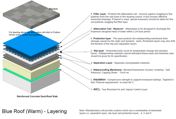
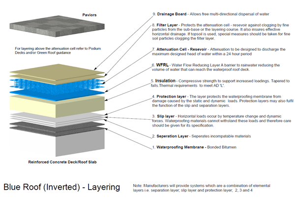
Blue roof layering: detailing
References and further guidance (references as of February 2021)
- BS EN 1992-1-1:2004+A1:2014 - Eurocode 2: Design of concrete structures. General rules and rules for buildings
- BS 6229:2018 – Flat roofs with continuously supported flexible waterproof coverings - Code of practice
- BS 8102:2009 – Code of practice for protection of below ground structures against water from the ground
- BS EN 12056-3:2000 – Gravity drainage systems inside buildings - Roof drainage, layout and calculation.
Guidance Notes:
- Technical Guidance Note for the construction and design of Blue Roofs - NFRC
- The SuDS Manual - CIRIA 2015
Rainfall Models: - The Flood Estimation Handbook (FEH) 2013 – UK SuDS
- Flood Studies Report (FSR)
- OFWAT, 2010 - Changes in the frequency of extreme rainfall events for selected towns and cities
