Introduction
Gable spandrel panels can be used as a continuation of the internal skin of masonry cavity blockwork. Where this occurs, the panels must be designed to resist wind loadings acting on the end walls and also loads applied by the claddings. Some of the key Warranty risk areas associated with gable spandrel panels will be highlighted in this article.
It is important that all spandrel panels, supporting structures and fixings, are designed by an Engineer to withstand all applied vertical and horizontal loads, on a site by site basis and not a generic solution.
Please note, erection procedures and temporary restraint requirements are outside the scope of this guidance.
Download a PDF copy of this guidance.
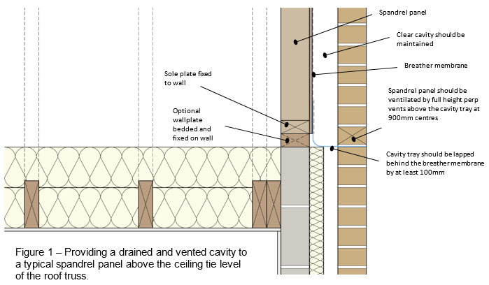
Providing a drained and vented cavity
Gable spandrel panels are essentially a form of timber frame construction, and as such, they must incorporate a sheathing board, breather membrane and maintain a minimum of a 50mm clear cavity.
Full fill cavity insulation with not be acceptable for warranty as this prevents the Spandrel panel frame from being able to dry out.
The stud positions should be clearly marked on the breather membrane to assist in correct installation and positioning of wall ties.
In a masonry cavity wall where blown full fill insulation is being used – below the Spandrel panel, there should be a way of insuring that the insulation does not deform the cavity tray or spread into the spandrel panel cavity frame area by incorporating a non-deformable cavity closure or ridged preformed cavity trays.
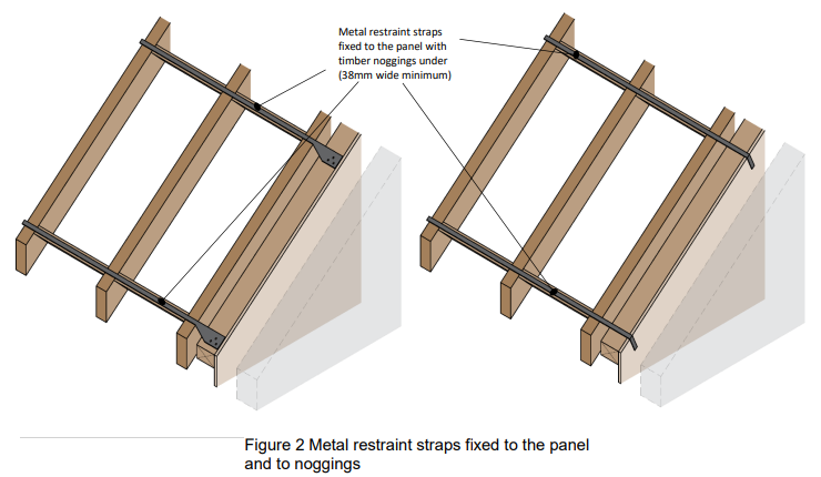
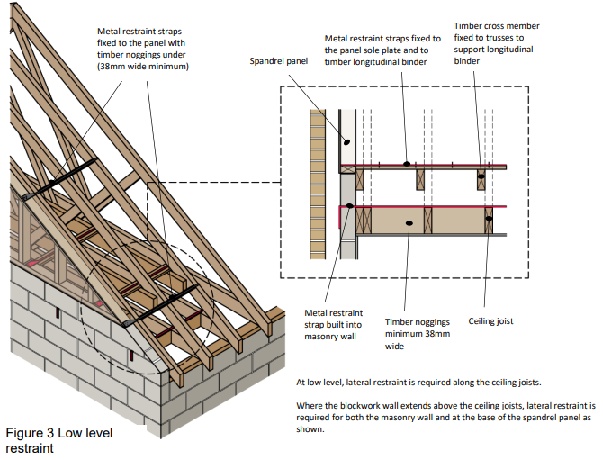
Lateral restraint
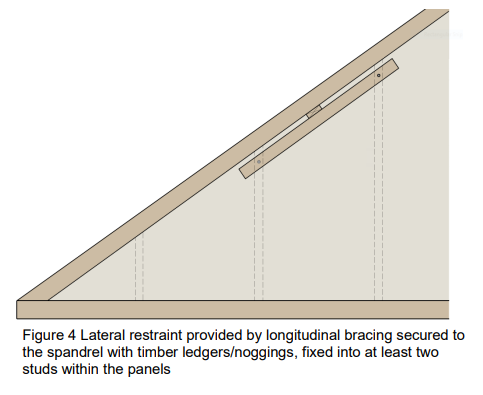
Spandrel panels require lateral restraint at rafter level and along the base of the panel (see figures 2 and 3). Lateral restraint could be provided by:
- Timber members (e.g. the longitudinal bracing secured to the spandrel with timber ledgers/noggings), fixed into at least two studs within the panels (see figure 4).
- Metal restraint straps fixed to the panel and to noggings, or timber bracing fixed across the trusses (see figure 2).
Gable spandrel panels must resist wind loads acting on the gable end walls and loads transferred from elsewhere e.g. from the roof structure, bracing etc. These loads are transmitted through the panel from the roof structure, bracing etc. via lateral restraints.
The restraint of the panels, should be designed by an Engineer to withstand all applied vertical and horizontal loads, on a site by site basis to suit the structural requirements of each project. The design and supporting calculations should be provided to the Warranty Surveyor.
Wall tie locations
Wall ties between the spandrel panel and brick or block outer leaf should have the ties fixed into the timber vertical studs of the spandrel panel. The spacing of wall ties should be increased at the top of the wall and where a potential slip plane is present (horizontal cavity trays at the base of the spandrel panel).
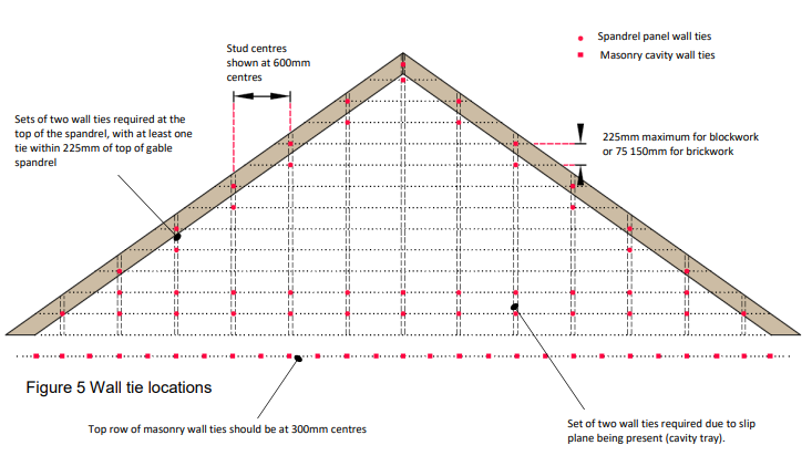
Notes:
- For the general spandrel panel area, wall ties should be at every stud centre and at 450mm max vertical centres
- The stud positions should be clearly marked on the breather membrane to assist in correct installation of wall ties
- Block coursing shown in the above image. Wall tie spacings to be determined by the Design Engineer
Fire spread
Fire spread from gable end spandrel panels is dependent on a number of factors and its distance from relevant boundaries. Advice should be sought from your Building Control Body for further information.
Warranty stance
As highlighted in this article, there are a number of risk areas when specifying gable end spandrel panels. In all circumstances, it’s important to ensure a designer is involved prior to associated works starting on site. It is important that the spandrel panels, supporting structures and fixings, are designed by a suitably experienced Chartered Engineer to withstand all applied vertical and horizontal loads, on a site by site basis.
