
What is the issue/risk?
This deflection will at some point need to interface and interact with the heads of non-load bearing internal wall, and even though the reality is that they are not intended to be loaded, if a wall is built tight up to the underside of the floor, it will take some load from the floor.
If deflection of the floor is not factored into any wall built underneath, it will have accidental load imposed upon it by the structure above. This accidental loading can cause the wall to bend, potentially cracking finishes and causing other problems such as creaking of floors, hogging (upward bend in the floor), etc. In multiple storeys, it may also load the floors below which may cause over-stressing.
For example, when you have a heavily loaded structural timber beam that is spanning 4m or more, it may designed to deflect up to 14mm or 0.003 x L at mid-span. If you have a non-load bearing timber stud wall located under the middle third of such a beam, the beam may impart a load onto the stud wall which it is not designed for. Timber beams that require particular consideration in domestic housing tend to be trimmers around staircases that are supporting other beams. These types of beams have a tendency to be laminated veneer lumber (LVL) which is engineered using multiple layers of thin wood assembled with adhesives or maybe standard engineered I-joists, dependent upon span and loading.
Warranty stance
For the purpose of our Warranty, site specific designed deflection allowances should be clearly defined by those designing the floor structure. The building designer should clearly indicate walls that are suitable for structural loading and walls that are not.
This should be factored into the design of any internal non-load bearing walls, and head restraint details must correspond with identified and expected deflection limits. A corresponding deflection head design should be provided prior to commencement of any construction of internal non-load bearing walls.
Other considerations
‘Wall’ type
There are various types of internal wall construction e.g. masonry, metal and timber. In every instance, the underside of floors are frequently used to provide anchorage at the head of the partition and provide the required stability levels in the internal wall.
Irrespective of the wall construction type, the restraint of the wall at its head and any designs must allow or transfer any allowable deflection within the chosen floor structure into its union with the underside of the floor:
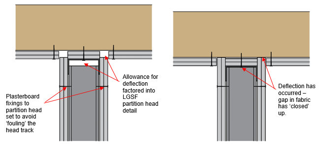
Metal: Light gauge steel framing sections can be used to create non-load bearing walls. This approach uses a telescopic head arrangement which allows the deflection to take place without putting any load on the wall below. This type of approach typically allows for a gap of up to a maximum 50mm.
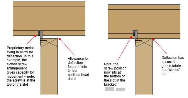
Timber: A prefabricated metal connector plate creates the anchorage between the top of a non-load bearing wall by connecting it to the floor joists above. It has a tapered slot which allows for any joist deflection when it is loaded, while still restraining the internal wall. Typically this type of fixing allows a maximum gap between the partition and the joist of 15mm.
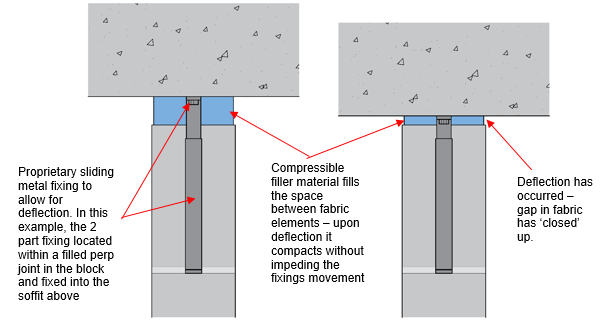
Masonry: A prefabricated steel connector is often incorporated to restrain the top of internal walls. Typically it comprises of a sliding channel and internal stem that slides down as the floor above deflects accommodating vertical movement between the blockwork and the floor structure. The joint itself is often filled with compressible material in between fixings. Typically this type of fixing allows a maximum gap between the wall and the structure of 50-75mm.
Fire performance
The inclusion of deflection head detailing must not be detrimental to any walls that are required to resist the passage of fire. Where the wall construction is supplemented by fire testing evidence, the deflection head detail should be included within the fire resistance testing for the complete assembly as tested or assessed. Where it is not, deflection head detailing that is also required to perform a fire resisting function must be assessed by an appropriate Engineer and perform to the satisfaction of the authority holding jurisdiction over fire compliance approval e.g. Building Control Approver, Fire Engineer.
Fire stopping
The interaction of fire stopping materials and deflection head detailing may be required to seal any imperfection of fit between fire-resisting walls and other elements such as adjoining structure or cavity barriers, and to seal around any services which may penetrate the partition in and around the deflection head detailing. In such instance, the materials and approaches chosen must be assessed by an appropriate Engineer and to the satisfaction of the authority holding jurisdiction over fire compliance approval e.g. Building Control Approver, Fire Engineer.
Smoke control
Similarly, where the interaction and detailing of deflection heads and products used to seal against the passage of smoke is required, any approaches must be assessed by an appropriate Engineer and to the satisfaction of the authority holding jurisdiction over fire compliance approval e.g. Building Control Approver, Fire Engineer.
Acoustic performance
Where an internal wall is to provide sound insulation, any deflection head detail should be fully assessed in relation to its acoustic performance in service.
Services
The fixing of services or the passage of services should be fully considered, notably where they pass through the heads of walls, either laterally or vertically.
Please note
This article should also be read in conjunction with our ‘Good practice for metal web joist installations’ article.
