Timber Framed Modular Build Systems
LABC Warranty’s stance on timber framed modular build systems, including hybrid systems which incorporate a steel frame with Structural Insulated Panels (SIPs) or Cross Laminated Timber (CLT) infill panels, remains unchanged. The requirements relating to timber frames given in Section 6 of the Technical Manual must be applied. Quoting the manual:
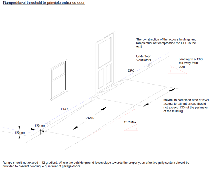
“All structural timber should be located at least 150mm above finished external ground level, except for localised ramping (incorporating satisfactory drainage and ventilation detailing) for level threshold requirements.”
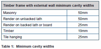
It is also important for both light gauge steel frame (LGSF) and timber framed buildings to remember that a breather membrane should be provided and all external wall claddings should be separated from the frame structure by a drained and ventilated clear cavity, provided with the minimum widths outlined in the table below.
Steel Framed Modular Build Systems
Light gauge steel frame (LGSF) floors are becoming more common as a solution to the floor construction with MMC systems. However it is becoming increasingly common to insulate above the floor joists. This and the desire of architects to raise external ground levels is pushing the LGSF joists and base rails further below the recommended 150mm above external ground level and in many cases we are seeing proposed designs where the entire floor construction is pushed below external ground level.
This article aims to provide guidance for modular systems where the developer is intending to locate the base rail and or joists below 150mm above external ground level. However this does not cover where the LGSF base rail or joists are intended to extend below ground level. Base rails or joists located below ground level do not meet our Warranty requirements and an alternative solution should be found.
Conditions for LGSF floors less than 150mm above external ground level
For modular systems where the underside of the base rail and/or joists is less than 150mm above external ground, but not lower than external ground level, even on sloping sites, the following conditions apply:
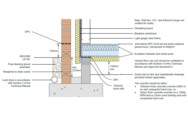
a) Where any steel member is located less than 150mm above external ground level, but not lower than external ground level, it must be galvanized to a minimum standard of 600g/m2.
b) As the external ground level will be higher than the oversite concrete (solum), a land drain must be provided to the perimeter of the building in accordance with the Section 2.1.4 of the Technical Manual.
c) The sub-floor void oversite concrete (solum) must be laid to falls and a maintainable drainage channel/gulley provided to remove any seepage of water building up from the sub-floor void area. However, where site conditions permit (permeable ground conditions only), the sub-floor void drain, may be omitted if a ground condition report is provided and only where this is agreed in advance.
d) Where localised areas of external ground level (max.15% of the perimeter) need to be raised above the base rail and/or joists for level access arrangements, a suitable waterproofing design must be provided.
e) The construction of the ground floor must meet the requirements of Regional Building Regulation Standards for structure, site preparation, resistance to moisture & contaminants
f) The sub floor void should be ventilated in accordance with Section 4 – Ground floors of the Technical manual.
g) Any external wall finish or sheathing board used below 150mm should have suitable third party product conformity certification to be used below DPC.
h) Suitable provision of drainage from external wall cavity should be provided.
i) Thermal modelling of the ground floor/base rail junction may be required to demonstrate that any issues with thermal bridging or interstitial condensation will not occur.
The detail below has been produced to provide further clarification of the above conditions:
Sub floor ventilation requirements
Sub-floor ventilation must be provided and give a free cross flow of air. Ventilation should be provided in two opposing walls so that the ventilating air will have a free path between opposite sides and to all parts. The opening area for ventilation should not be less than either 1500mm2/m run of external wall or 500mm2/m2 of floor area, whichever is the greatest. The table below gives examples of floors area calculations at 500mm2/m2
|
Floor area of building (m2) |
Minimum ventilation provision (mm2) |
| 40 | 20,000 |
| 60 | 30,000 |
| 80 |
40,000 |
| 100 |
50,000 |
| 120 |
60,000 |
| 140 |
70,000 |
| 160 |
80,000 |
Level access arrangements
Where localised areas of external ground level (max.15% of the perimeter) need to be raised above the base rail and/or joists for level access arrangements, a suitable waterproofing design must be provided. Where level access is to be provided; a thickness of corrosion protection equivalent to 600g/m2 galvanising should be maintained to all components below DPC level. However, the access ramp should be limited to the entrance door area only (not the entire perimeter) and provision for a slotted drainage and the ramp should be provided with a gradient away from the door (see the Section 8 of the Technical Manual 'Windows and Doors' section for level threshold guidance)