
Provision of information
A full set of structural calculations and drawings shall be made available to the Warranty provider and all other interested parties prior to the associated works starting on site. This may include:
- Spacing and location of movement joints.
- Wall tie spacings around movement joints.
- The materials to be used for the compressible filler and sealant.
- Mortar bed joint reinforcement type, location and length if required.
The above must be in line with the requirements set out in chapter 6 of our Technical Manual, PD6697 and EN 1996-1-1: Eurocode 6.
The Warranty surveyor, at their discretion, may also request supporting information that demonstrates suitability for use of any materials or systems contained within the above.
What are movement joints and why are they important?
Buildings by many, may be seen as inert or static objects, however, in actual fact they are prone to a considerable amount of movement, primarily due to environmental factors such as variations in temperature and moisture. Movement joints (sometimes referred to as expansion joints) are often introduced within the design and it consists of a gap which allows for expansion and contraction. The gap is filled with a compressible filler and a weatherproof sealant is layered on top.
Having no movement joints (or movement joints at the incorrect spacings) can therefore cause stress cracking in the external wall (and adjacent elements) as sufficient allowance has not been catered for expansion and contraction.
Movement joint requirements in masonry
Spacing of movement joints
For masonry walls, movement joints should be spaced as per the table 1 (as reproduced from our Technical Manual).
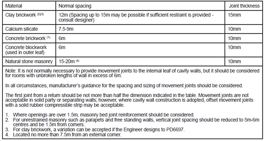
Window and door openings effectively divide external masonry walls into a series of panels. As such, external wall leafs of masonry should be designed as a series of panels separated by movement joints to control movement. Movement joints should be spaced as per table 1 and the ratio of length to height of the panels should generally not exceed 3:1.
Positioning of movement joints
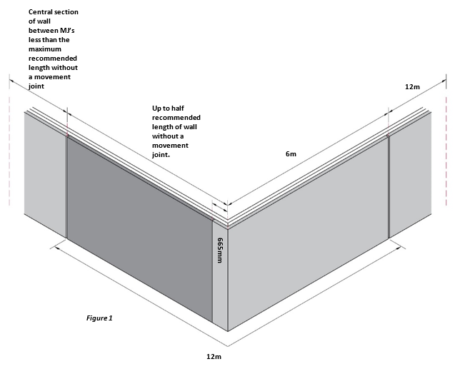
For masonry cavity walls, horizontal expansion will occur at corners which can push the corners out and this in turn can eventually cause cracking, however this can be avoided by sub-dividing walls into shorter lengths with movement joints. Movement joints should also be provided as close to corners as possible (but not less than 665mm from a corner).
The shaded area in figure 1 shows the ideal position for the first movement joint – first movement joint should be no less than 665mm from a corner and up to half recommended length of wall without a movement joint.
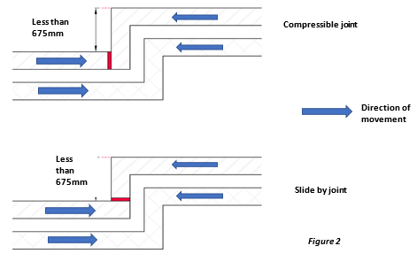
Short returns in clay masonry (less than 675mm) should have movement joints as per figure 2 below. Movement joints can be specified with the use of a ‘compressible joint’ or a ‘slide by joint’.
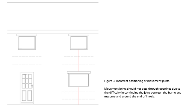
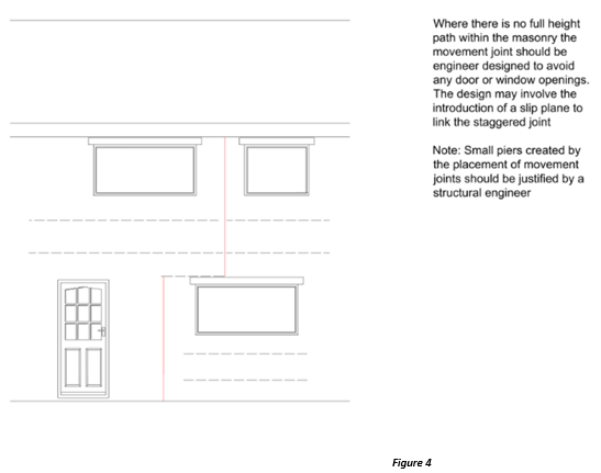
Movement joints should not pass through structural members e.g. lintels. Movement joints should not coincide with door or window openings due to the difficulty in continuing the movement joint between the frames and masonry and around the ends of the lintels. Vertical movement joints should therefore be located in sections of full height masonry between the openings.
Where a full height masonry panel does not exist, the location and detailing of the movement joint should be designed by an Engineer.
Wall tie positioning adjacent to movement joints
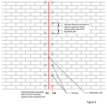
Wall ties should be spaced as per figure 5. A Structural Engineer would need to provide justification and calculations for any deviation.
For timber framed structures, maintaining a 225mm horizontal wall tie spacing can be difficult as the timber studs may be more than 225mm away from the movement joint.
Introducing additional timber studs may be impractical and therefore an alternative solution of using slip ties at 300mm vertical centres with 50mm embedment into the masonry either side of the movement joint, could be considered subject to a Structural Engineers design.
Parapets
Unrestrained masonry such as parapets and free standing walls require greater movement control due to their greater exposure, less restraint and stronger mortar mixes. Movement joint spacing for parapet walls should therefore be half then what is stated in table 1 and 1.5m from corners. For further guidance on movement control in parapet walls, the Structural Engineer should be consulted. For further guidance on parapets, please see our ‘Guide to Creating Weatherproof Parapet Walls.’
Materials
To meet our warranty requirements, compressible filler, such as polyurethane foam, should be used to form the joint and be sealed to prevent water penetration and achieve a service life of at least 15 years (without maintenance). Movement joints should be sealed with an appropriate sealant which can provide sufficient flexibility whilst resisting water penetration. When sealants are used in proximity with stone it is important to select a non-oil-based sealant to help prevent any staining to the stone.
Elastic sealants (Type E) are suitable as they allow for reversible movement. Where a back-up material is used to control the sealant depth, it will also provide a compressible space into which the sealant can deform.
Where a backing material is used, the following must be considered:
- The material is compatible with the sealant.
- It will not adhere to the sealant, preventing cracking within the sealant.
- Provides sufficient density to allow the sealant to be applied.
- Allows sufficient flexibility so not to impede lateral movement (compressible to about 50% of its original thickness).
- Please note, Hemp, fibreboard, cork and similar materials should not be used for expansion joints in clay brick masonry, but may be used for contraction joints in calcium silicate and concrete masonry (PD6697).
Allowances for compression thickness of the sealant must allow for the specified movement joint width plus the non-compressible thickness of the seal.
Movement joints in concrete bricks
The rate and extent of movement in concrete bricks can be considerably different to that of clay bricks.
Concrete shrinkage is due primarily to the shrinkage of the hardened cement paste. The type and amount of aggregate can affect the amount of shrinkage in a concrete bricks performance.
- Sandstone Aggregate: Typical 1 year shrinkage @ 0.116%
- Granite Aggregate: Typical 1 year shrinkage @ 0.047%
- Limestone Aggregate: Typical 1 year shrinkage @ 0.032%
With the high differential of movement between the various available raw materials used in concrete brick manufacture it is imperative that the design for movement in a wall panel is specific to the shrinkage capacity of the concrete brick used and the requirements of the manufacture should be followed. In all cases site specific advice should be obtained from the manufacture before work begins.
Accounting for movement in framed structures
Anticipated differential movement for timber frame structures
Differential movement can occur with timber framed buildings where the overall height of the timber frame will reduce due to shrinkage as the timber frame dries out predominantly within the first 24 months of completion. Other building components, such as brick and blockwork may increase in height due to thermal expansion and moisture related movement. This differential movement between the cladding and timber frame must be allowed for in design.
Differential movement can also occur in a variety of other locations in and around a building.
These may include:
- Windows and doors
- Balconies and Juliet balconies
- Openings for services
- Eaves and verges
- Cavity wall ties
- Battens across floor zones
- Junctions for mixed cladding designs
- Lift shafts and stair wells of mixed construction
For a typical softwood timber element, allow a 1% shrinkage across the grain for every 4% reduction in moisture content. This means that 1mm should be allowed for differential movement for every 38mm of horizontal solid timber. This formula does not apply to engineered wood products. Typically, 2mm–3mm of differential movement allowance for compression and settlement of floor joists that use engineered wood products will be sufficient. Shrinkage of the solid timber horizontal plates and rails must still be allowed for however.
Any material or component attached to the timber superstructure that overhangs the brick or blockwork (e.g. cladding attached to the timber frame, window sills, roof eaves, and verges) or projects through the masonry (e.g. balcony supports, flues, extractor fan vents, or overflow pipes) should have a clear gap beneath and at the top of the masonry cladding to allow differential movement to take place, thus avoiding damage to the components or cladding.
Where masonry cladding is specified for a timber framed building, the building should be designed to ensure that differential movement occurs evenly to external elevations and the internal structure. Site specific calculations should be used to determine movement gap sizes, however in absence of site specific calculations, table 2 can be used for buildings up to five storeys.
For the purposes of Warranty, a storey is defined as a space between two consecutive floors or between a floor and a roof. The number of storeys should be counted from the lowest external ground level and it should include the ground storey.
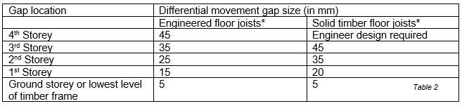
The compressed thickness of the material used to fill the gap must be added to the dimensions given in table 2.
- For eaves and verge, add 5mm to the dimensions given in table 2.
- The product used for differential movement must be capable of compressing without causing undue stress to the surrounding construction.
- Where masonry extends continuously below the lowest level of timber, brickwork expansion should also be taken into account.
- Moisture content of all timber must be less than 20%.
- Table 2 is based on a concrete ground floor. Where timber joists are used at ground floor level, 15mm for solid timber joists and 10mm for engineered I-Joists should be added.
- Table 2 assumes outer leaf brickwork with expansion rates no greater than 2.5mm per storey.
- Services that are rigid from the foundations, e.g. soil stack, dry riser, gas and water, require differential movement gaps above the service entry. The gaps should be equal to those recommended for the bottom of openings at the appropriate floor level.
- There should be consideration for differential movement at lift door/thresholds and at the top of self-supporting element such as masonry or steel lift shafts.
- Table 2 based on a maximum depth of timber joists and rim beam/header to be 240mm.
- Single head binder at the eaves. Maximum double sole plates.
We have more detailed guidance on catering for differential movement in timber framed buildings within the ‘External Walls – Timber Frame’ section of our Technical Manual.
Accounting for movement in Light Gauge Steel Frame
Light gauge steel frame (LGSF) structures will also move at a different rate compared to the external cladding and this should be taken into account by the Structural Engineer. Movement joints should also be located under openings, eaves and verges.
In addition, any material or component attached to the LGSF structure that overhangs the brick or blockwork (e.g. cladding attached to the LGSF, window sills, roof eaves, and verges) or projects through the masonry (e.g. balcony supports, flues, extractor fan vents, or overflow pipes) should have a clear gap beneath and at the top of the masonry cladding to allow differential movement to take place, thus avoiding damage to the components or cladding.
Movement joints in render
Rendered walls should be constructed with control measures in place to reduce the risk of damage to the render from movement in the substrate.
Rendering onto masonry walls
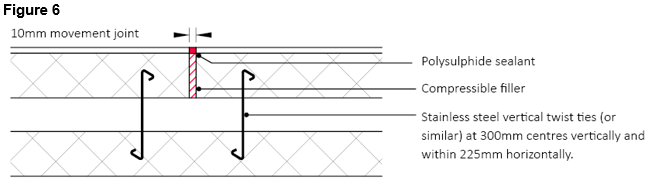
Any movement joints within the substrate should be carried through to the face of the render (figure 6).
Where recommended by the blockwork manufacturer, cracking of the substrate could be significantly reduced by introducing a specialist proprietary bed joint reinforcement within the mortar joints. This should be provided in accordance with the Structural Engineer’s specification.
Ensure that the reinforcement is continuous and joints lapped in accordance with the manufacturer’s requirements (generally 450 - 500mm laps and continued around corners). Specialist corner units are likely to be required, check with the block manufacturer.
Introducing bed joint reinforcement at weak points such as above and below window and doors openings will greatly assist in minimising cracking to these areas. Where possible, the reinforcement should project 600mm beyond the opening.
Render should not bridge across dissimilar materials, however if this cannot be avoided, the render should be stopped at an appropriately formed movement joint or austenitic stainless steel lath reinforcement should be used across the joint with a separation strip behind.
Rendering onto render board and timber/steel framed structures
Note: Render boards must be proven to meet a relevant BS EN standard and proven suitable as a direct render board e.g. BS EN 12467 to a category A weather resistance and have third party product approval by a UKAS )or international equivalent).
Gaps between boards should be provided in accordance with the manufacturer’s recommendations and carried through to the face of the render. Care should be taken to ensure there are no excessive gaps between the boards and appropriate weather seals are incorporated against walls and frames.
Where renders spans across an intermediate floor zone in timber frame construction, allow for differential movement due to timber shrinkage by incorporating a horizontal movement joint.
Vertical movement joints should be provided at the required intervals. The actual spacing and position of the joints will be determined by the shape of the area to be rendered and generally vertical movement joints should be provided at maximum 5m centres.
For further guidance on render boards, please refer to our ‘External Walls – Render’ section of our Technical Manual.
Mesh reinforcement around openings
For rendering onto both masonry and render board, mesh reinforcement is required around openings as per figure 7 below.
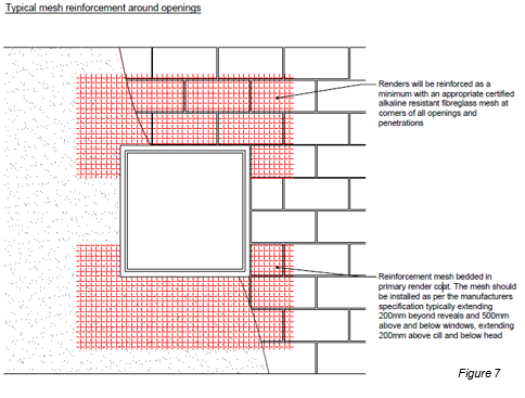
In summary, prior to works starting on site, rendered walls and their anticipated movement should be considered as part of the design by the Structural Engineer.
Other considerations
Differing materials
Brickwork and other building materials move at different rates and therefore where differing materials abut each other there should be consideration for how the movement is to be accommodated by your structural engineer (movement joints, bed joint reinforcement etc.).
On any given wall elevation where there is a mix of masonry e.g. Brickwork external leaf lower level with a rendered block upper level, the requirement of a full height movement joint should be based on the shorter spacing requirement e.g. for the blockwork at 6m - not brickwork at 12m.
Changes in height
A movement joint should be considered where there is a significant change in height in the building elevation. This can be achieved with the use of a compressible or slide-by joint and should run the full height of the building.
Bed joint reinforcement
Bed Joint reinforcement may also be required to critical areas to accommodate stresses such as above and below window openings. The Structural Engineer or render manufacturer may require this to be provided as part of the overall design specification. Where provided, they will be in addition to movement joints, not instead of. Bed joint reinforcement potentially can increase spacings of Movement joints subject to the Structural engineer’s specification.
Movement joints below DPC
Where the finished ground level is 600mm or greater below the horizontal DPC, the movement joint should be continued within the external leaf of the sub structure.
Building orientation
The orientation of your building can have a substantial impact on the movement of different materials due to temperature changes. Allowance should therefore be made for south, south west, south east and the rear face of north facing parapets to move in a controlled manner with the use of movement joints and/or bed joint reinforcement. The structural engineer and render manufacturer should provide a project specific specification.
Retrofitting movement joints
Movement joints must be considered and detailed at design stage and discussed on site before any works begin. Their positions must be fully communicated to the site team and relevant trades before bricklaying begins.
In instances where they’ve been missed on site, a structural engineer should be consulted to provide a designed solution and the following should be considered:
The Structural Engineer must provide a specification of:
- Spacing and location of movement joints.
- Wall tie spacings around movement joints.
- Provision of slip ties.
- Type of sealant and backing material.
- A detailed method statement for how this is to be achieved.
Induced movement joints are not recommended (e.g. retrospective cuts in completed panels with a petrol stihl saw) as these rarely achieve full depth of the cut and required width of joint) and the necessary wall tie provision may not be in place either.
Warranty stance
The provision of movement joints should be considered at an early stage by your designer and they should meet the requirements of our Technical Manual, PD6697 and EN 1996-1-1: Eurocode 6.
References
- PD 6697:2019 Recommendations for the design of masonry structures to BS EN 1996-1-1 and BS EN 1996-2
- Designing for Movement in Brickwork, Brick Development Association
- Design and specification considerations designing for movement, IB Stock
- Accommodating Movement in Building Envelope Materials, The Building Envelope
